9
Filter tank
1. Insert the standpipe (7) with the lter screen (19) into the tank (12) (Il-
lustration 2) until the standpipe with the lter screen reaches the bottom
of the tank (12).
2. Make sure that the standpipe (7) is in the middle. The drainage screw
(11) of the tank should be inserted.
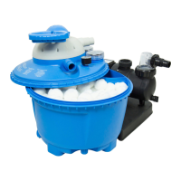
3. Remove the Filter Balls from the plastic wrapper and ll the
Filter Balls into the tank. Please note that the Filter Balls
must be lled loosely and should not be pressed down or
squeezed. This signicantly affects the lter performance.
4. Now place the centring device on the tank open-
ing, thereby centring the standpipe (7). (Illustration 4)
5. Before you install the valve head (1), it is imperative to clean the seal-
ing surfaces (3 + 4) and screw connections/threads again and to wash
off residues or dirt. The connection of the valve head to the lter tank is
done using the clamping ring (6) The clamping ring is screwed together
with the clamping ring screw and clamping ring screw nut. (Illustration
5 and 6 + 7)
6. Finally, mount the connecting pieces on the valve head (1). Seal the
connecting pieces sufciently for installation with a sealing tape.
7. The pressure gauge (2), if included in the scope of delivery, is mounted
and sealed at the side of the 7-way valve. The existing bleed screw
should be removed rst. (Illustration 9)
Hose connections pump (Illustration 8)
1. Skimmer pipe: Connection from the skimmer
connection to the front connection on the lter pump.
2. Pressure pipe: Connection from the top connection of the lter
pump to the connection labelled “PUMP” on the 7-way valve.
3. Return pipe: Connection from the connection on the 7-way
valve labelled “RETURN” to the connection on the inlet
nozzle (pool). Fix all the connections with hose clamps.
4. Backush pipe: Connection “WASTE” (emptying)
into the channel. The connections are to be made
with special swimming pool hoses and hose clamps!
Filter system installation instructions
Once the lter system is completely assembled, the Filter Balls are in the
tank and all inlet and outlet pipes are connected, commissioning can continue.
Do not turn on the power until this is expressly mentioned.
■ Make sure that the power cord (electric cable) of the pump is
disconnected from the mains.
■ Ensure that the valve lever is in the “closed” position.
■ Make sure that the lter system is located outside the pool and lower than
the water level of your pool, and that all inlet and outlet pipes are properly
connected and xed.
■ If your pool is not lled yet, ll it with water. Make sure that the water level
of the pool is at least 2.5 to 5 cm above the opening of the lling nozzle
(skimmer).
■ Open the shut-off valve on the lling nozzle (skimmer) of the pool. If you
have closed the lling nozzle (skimmer) with a plug, remove it now.
■ As the position of the lter system is lower than the water level of the
pool, the lter system now automatically lls with water.
■ The lter system should now be vented. If applicable, ensure that the
lter pump’s pre-lter guard is slightly open until the water runs from the
pre-lter container (transparent lid with screw tting on the upper surface
of the lter pump).
■ Allow the lter container to run full of water.
■ Check the lter system, as well as the connections of the inlets
and outlets, for leaks. Leakage points may possibly arise due to
manufacturing tolerances, which need to be resolved by wrapping sealing
tape around the connections before the connection hose is attached.
■ Set the 7-way valve into the lter position.
■ Connect the pump to the power supply.
■ Your lter system is now ready for use.
Backwash procedure
In contrast to standard lter systems with sand lling, for a lter system with
Filter Ballsno backwashing should be carried out. If the lter performance
should decrease, we recommend washing the Filter Balls by hand.
If necessary, the Filter Balls should be replaced.
Filter modes
Settings Complete water ow or function
Filter Function: Suction, normal lter operation. In this position,
the pool water sucked in is introduced from above into the
lter tank, and ows through the Filter Balls. In the process,
impurities are ltered out and the water is then returned to
the pool.
Rins
e
Function: This process should take place after initial start-
up. In this position, the water is introduced into the upper
area of the lter tank and the valve rinsed. The water ows
through the soil pipe again.
Circulation Function: Circulates the water after a chemical treatment.
This position is used when performing chemical treatments
on the pool water, if is not desired that the Filter Balls come
into contact with the treatment chemicals. In this position,
the water sucked in is returned directly from the valve to the
pool, without owing through the Filter Balls.
Back
wash
In contrast to standard lter systems with sand lling, for
a lter system with Filter Ballsno backwashing should be
carried out. You will notice that it is time to clean the Filter
Balls when the pressure gauge pressure is 0.3 to 0.6 bar
above the normal operating pressure. If the lter perfor-
mance should decrease, we recommend washing the Filter
Balls by hand.
If necessary, the Filter Balls should be replaced.
Closed Function: Cleaning the pre-lter. This position stops the ow
of water into the pump and lter.
CAUTION: Never turn on the pump in this position.
Emptying Function: Bypass the lter. This function is ideal for empty-
ing heavily contaminated pools or after an algae treatment.
In this position, the lter is bypassed and the water is
discharged directly through the soil pipe.
Winter Function: Wintering and storage. In this position, the valve
lever is in an intermediate position. In this way the internal
valve components are relieved. If the lter system is stored
in winter, turn the 7-way valve to this position.
CAUTION: Never turn on the pump in this position.
Filtering time
The swimming pool’s water should be circulated and ltered at least
3 to 5 times in a 24 hour period, depending on the load and the size
of the lter system. The time required is based on the performance
of the lter system and the size of the swimming pool. However,
we recommend a minimum running time of 12 hours per day.
Electrical connection
The lter system you have purchased is equipped with a connection cable,
which may only be connected to a circuit with a residual current circuit
breaker (RCCB) with a rated residual current of no more than 30mA.
Technical data:
■ Circulation power 3,800 l/h
■ Pump is not self-priming
■ maximum water temperature 35 °C
■ 230 V / 200 W
■ 7 way valve with pressure gauge
■ Tank Ø 250 mm
■ Connector Ø 32/38 mm
■ Base plate
■ for pools up to 19,000 l capacity
■ Optional: Speedpart Container for UV system Speed UV
 Loading...