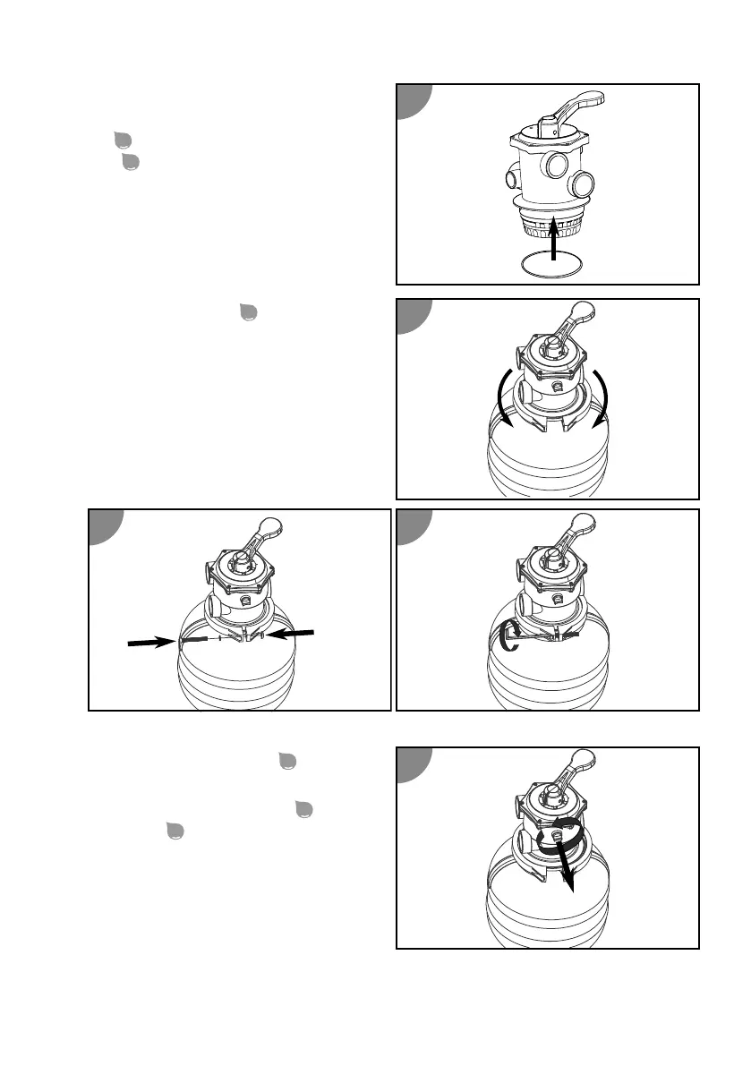
12. If the vessel seal is not already ed
on the valve head, guide the vessel
seal
over the boom of the valve
head
.
13. Place the valve head on the lter
vessel.
14. Align the valve head so that the
"PUMP" connecon points towards
the future posion of the pump.
15. Place the locking ring
around the valve
head and lter vessel connecng point.
16.
Insert the screws of the locking ring and ghten them clockwise.
17. Remove the bleeder screw
on the valve
head by turning it counter-clockwise.
18. Wrap the manometer thread
with
Teon tape
.
19. Screw in the manometer at the removal
posion of the bleeder screw by turning it
clockwise.
52