Panel Controls and Terminals
UR12 Operation Manual 3
Panel Controls and Terminals
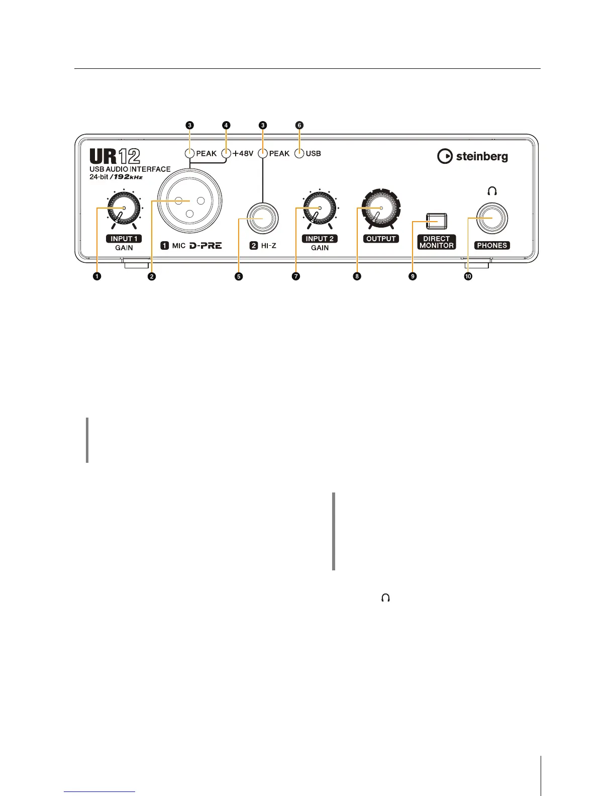
Front Panel
1 [INPUT 1 GAIN] knob
Adjusts the input signal level of the [MIC] jack.
2 [MIC] jack
For connecting a microphone.
3 [PEAK] indicator
Lights up when the input signal is 3dB below the
clipping level.
4 [+48V] indicator
Lights up when the [+48V] switch (phantom power) is
turned on. The [+48V] switch is on the rear panel.
5 [HI-Z] jack
For connecting instruments with a high output
impedance, such as electric guitars and basses. Use a
phone-type (unbalanced) cable for connection.
6 [USB] indicator
Lights up when the power is turned on. If the computer
or iPad does not recognize the device, this flashes
continuously.
7 [INPUT 2 GAIN] knob
Adjusts the input signal level of the [HI-Z] jack.
8 [OUTPUT] knob
Adjusts the output signal level of the [PHONES] and
[LINE OUTPUT] jacks. The output signal level of the
[PHONES] and [LINE OUTPUT] jacks are adjusted
simultaneously.
NOTE
Whenusingheadphones,turndownthevolumeoftheamp
ormonitorspeakersthatareconnectedtothe[LINE
OUTPUT]jackbeforeadjustingthisknob.
9 [DIRECT MONITOR] switch
Turns the DIRECT MONITOR function on (O) or off (N).
When the DIRECT MONITOR function is turned on, the
audio signal sent from the computer and the audio
signal input from the [MIC]/[HI-Z] jacks are output
directly to the [PHONES]/[LINE OUTPUT] jacks.
) [PHONES ] jack
For connecting a set of headphones.
HINT
Setting optimum recording levels
Adjust the gain knobs so that the [PEAK] indicator
flashes briefly at the loudest input volume.
HINT
Using this switch
To monitor audio from the input jacks via the DAW
software (for example, when you also want to hear the
software effects), turn this switch off. If the software
latency bothers you, or if you always want to monitor the
input signal, turn this switch on.