09-282C 7 - 5 rev 8/97
ASSEMBLY section 7
INSTALLATION INSTRUCTIONS FOR CHIPPER/SHREDDER WIRE HARNESS ON MODEL 525
EQUIPPED WITH 2 SECOND DELAY RELAY
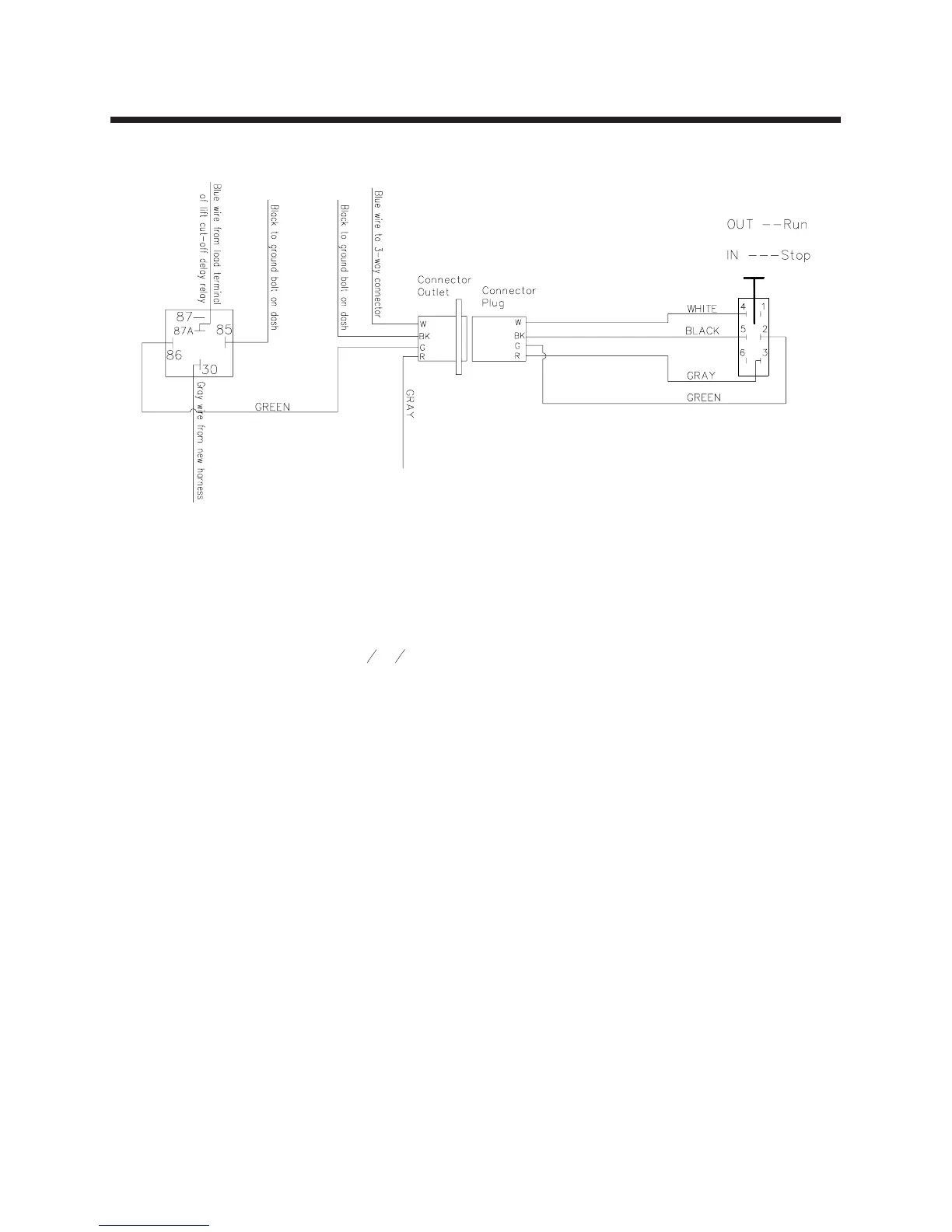
Wiring Diagram for Model 525 Tractors w/2 Second Delay
(after serial number 1197)
Model 525 Tractors:
1. Disconnect the battery ground cable.
2. Mount the electrical outlet on the left side of the
black upper grille panel with two
x flange
bolts and nuts. Choose a location using the
existing slots in the panel.
3. Remove the dash access panel. Starting at the
dash area, route the new harness (the end
without terminals) along the existing wiring
harness through the center pivot area of the
tractor. Continue routing until the wires reach
the electrical outlet.
4. Connect the new wire harness (Part # 30--301)
to electrical outlet installed in Step 2, following
the wiring diagram on this page. Connect the
black wire to the BK terminal, the blue wire to
the W terminal, the gray wire to the R terminal,
and the green wire to the G terminal.
5. Install the supplied relay to the same bolt that
fastens the top of the 30 amp breaker. Position
the relay so that the relay plug will clear the
other bolts on the electrical mounting plate.
6. Remove the blue wire from the load terminal of
the lift cut--off delay relay and install that wire in
the new relay plug so that it connects with the
#87a terminal of the new relay.
7. Install one of the gray wires from the new
harness (30--301) to the load terminal of the lift
cut--off delay relay. Either gray wire can be
used.
8. Install the other gray wire from the new harness
(30--301) into the new relay plug so that it will
connect with the #30 terminal of the new relay.
9. Install the supplied black wire (approx. 11” long)
to the new relay plug so that it will connect with
the #85 terminal of the new relay. Install the
eyelet end to the ground bolt on the dash. Also
install the black wire from the new harness to
the ground bolt.
10. Install the green wire from the new harness
(30--301) to the new relay plug so that it
connects with the #86 terminal of the new
relay. Install the relay plug onto the new relay.
11. Locate the light blue wire that goes to the
control terminal of the seat switch delay relay.
Cut this wire 3” to 4” from the delay relay plug
and install the supplied male bullet terminals to
both wire ends. Install both ends into the
supplied 3--way electrical connector, also
install the blue wire from the new harness
(30--301) into the 3--way connector.
12. Change the wiring on the emergency stop
switch following the wiring diagram on this
page. The white wire connects to the #4
terminal, the black wire connects to the #5
terminal, the green wire connects to the #2
terminal, and the gray wire connects to the #3
terminal.
13. Reconnect the battery cable, plug in the
chipper/shredder cable and test the
emergency stop switch for proper operation.
Pull the switch out for normal operation. Start
engine and engage the PTO. Push in for
emergency stop.
14. Replace all shields.
15. Proper operation will disengage the electric
PTO clutch when the emergency stop switch is
pushed “IN”. To restart, pull emergency knob
“OUT” and engage PTO in the normal manner.