INSSQBF0700607
A) INSTALLATION USING WOODEN HEADERS
Note: When using this method, the housing flange will rest flush against the wood frame in the ceiling.
1
PREPARATION
Before proceeding with the installation, plan ahead by taking into consideration the required clearances, ductwork and electrical wiring
involved. Make sure it will not impact the existing wiring.
2
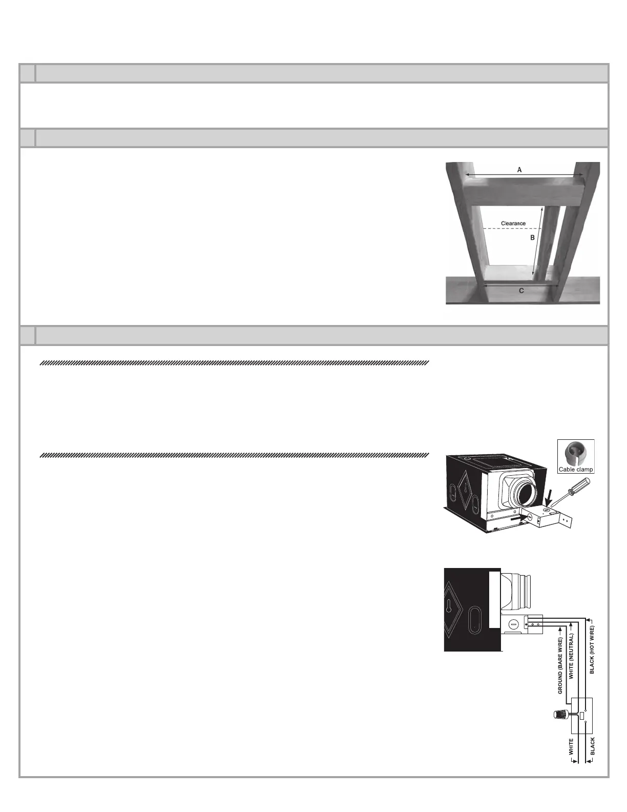
WOOD FRAME
Build a wood frame by adding headers to the existing ceiling joists in order to accommodate
the fan housing.
HEADER A – Header having a maximum thickness of 1 1⁄2’’ (e.g. 2x4), placed horizontally be-
tween the ceiling joists and nailed at each side. Must be laid flat and rest flush with the joists
to allow room above it for duct work and wiring. Length of this header is equal to the distance
between the joists.
HEADER B – Secured between headers A & C, this header must be spaced 9 1⁄2” from left
ceiling joist (see diagram). To facilitate ductwork and wiring, this header should be approxi-
mately 20 inches long.
HEADER C – Length of this header must be equal to the distance between the ceiling joists.
No specific thickness required.
3
ELECTRICAL WIRING
WARNING
A)
Before installing, switch off the appropriate circuit breaker in the electrical service panel.
B) Installation must comply with local and national electrical codes.
C) Must be installed by a certified electrician.
D) Unit must be properly grounded.
1- Remove wiring compartment cover and pry out one of the knock-outs. The cable clamp
(included) must be inserted through the knock-out hole. (Fig. 3.1)
2- Using the cable clamp, run a cable from the wall switch (not included) into the fan wiring
compartment.
3- Using connectors, attach the green wire coming from the fan to the bare wire (ground)
coming from the wall switch.
4- Using connectors, attach the fan wires located inside the fan wiring compartment to the
matching wires coming from the wall switch; black to black (hot); white to white (neutral).
(Fig. 3.2)
5- Replace wiring compartment cover.
Fig. 2.1
Fig. 3.1
Fig. 3.2
4