9
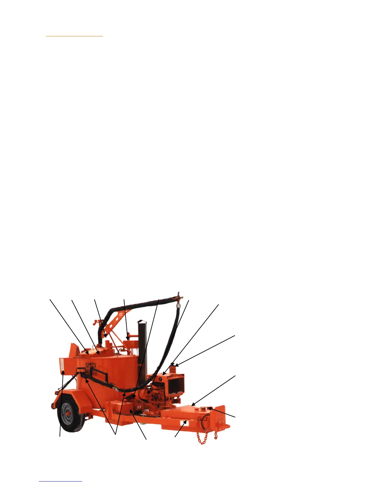
DESCRIPTION Component Location
1. Safety loading chute — Provides a "splash free" way of loading product into a "hot" tank.
2. Hood — Provides easy access to the inside of the tank for cleaning or "cold" loading.
3. Product pump motor — Powers the pump that pumps the product from the tank to the
wand.
4. Expansion tank — Provides room for the heat transfer oil to expand and allows the oil to
cool. This creates a "cold seal" effect allowing safer operation at elevated oil tempera-
tures.
5. Hydraulic pump — Provides hydraulic power to the heat transfer oil circulation pump, au-
ger, and the product pump.
6. 24 volt alternator — Provides electrical power to the wand and hose heating elements.
7. Engine control panel — Provides a means of controlling engine functions.
8. Engine fuel filter — Provides clean fuel to engine.
9. Hydraulic filter — Removes contaminates from the hydraulic system.
10. Hydraulic reservoir — Provides a 15 gallon capacity for the hydraulic system.
11. Fuel tank — Stores 30 gallons of diesel fuel to operate the burner and the engine.
12. Heat exchanger chamber — Exchanges heat from the burner to the heat transfer oil.
13. Wand & Hose — Provides a means of applying the product to the road surface.
14. Product pump control — Allows the operator to start, stop, or reverse the rotation and con-
trol the speed of the product pump.
3 2 1 4
5 6
7
8
9
10
13
12 11
14
 Loading...