5
SHA8
PROFESSIONAL 8-CHANNEL HEADPHONE AMP
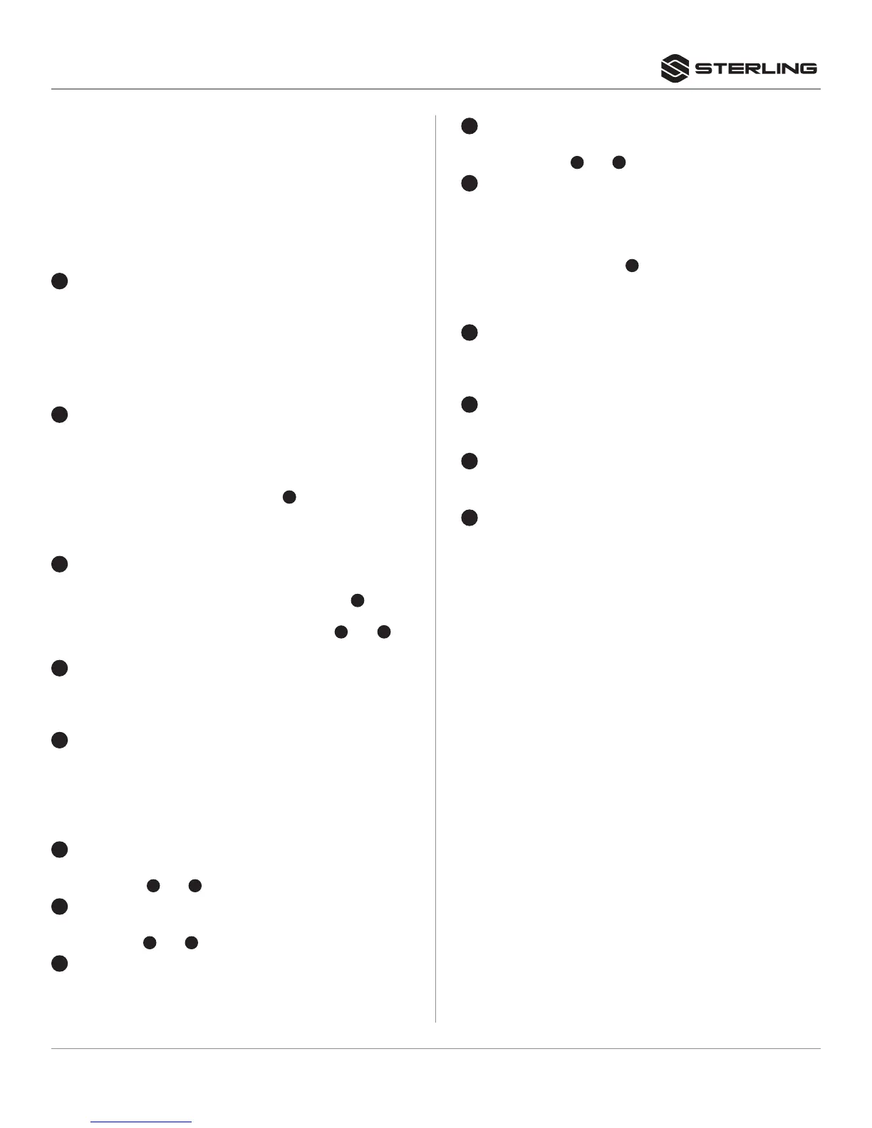
REAR CONNECTIONS
1
AC INLET AND FUSE HOLDER
Use the supplied AC power cable to connect the unit to AC
mains. The fuse can be accessed by the fuse panel below
the AC inlet. To change the fuse, unplug the AC cable first,
pull out the fuse panel and replace the fuse ONLY with a
fuse of SAME voltage and rating. If the fuse blows again
after replacement, hand over the unit to qualified service
personnel.
2
HEADPHONE REAR OUTPUTS (Channels 1 to 8)
These are stereo (TRS) outputs suitable to drive headphones.
While headphones down to 32 Ohms can be connected, a
higher impedance type (> 60 Ohms) is recommended for
lower distortion at high output levels. These outputs are
in parallel to the front-side outputs (
10
). Note that in case
headphones are connected to both front and rear outputs,
the load impedance will only be half, so headphones must
have a sufficiently high impedance.
3
DIRECT INS (Channels 1 to 8)
Stereo TRS inputs (unbalanced) allow a direct input feed for
a specific output channel. The assigned source (
13
) will be
disabled automatically if a connector is inserted here, and
the direct input signal is played at the output (
2
and
10
on
diagrams) instead.
4
MAIN INPUT R (Inputs 1 and 2)
Balanced input connector. This input shall not be used when
the source is mono, or shall be used as the right channel
input when the source is stereo.
5
MAIN INPUT L/Mono (Inputs 1 and 2)
Balanced input connector. This input shall be used when the
source is mono, or shall be used as the left channel input
when the source is stereo.
FRONT CONTROLS
6
INPUT LEVEL CONTROL A
Adjusts the input level of the signal connected via the
connectors (
4
and
5
) to channel A.
7
INPUT LEVEL CONTROL B
Adjusts the input level of the signal connected via the
connectors (
4
and
5
) to channel B.
8
INPUT LEVEL METER
Displays the input level of channels 1 and 2. Note that the
display shows both the INPUT 1 and INPUT 2 levels at the
same time.
FUNCTIONAL DESCRIPTION
The SHA8 is an 8-way headphone amplifier with 8 high-power
headphone amplifiers assignable to 2 individual inputs. Each
output has a mono/stereo switch and a LED level meter. Dual
front/rear connections and a direct input feature make this unit
suitable for a large variety of applications in recording, live sound
and installation environments.
9
OUTPUT LEVEL control (Outputs 1 to 8)
These controls set the outputs levels individually for the
relative output (
2
and
10
on diagrams).
10
HEADPHONE FRONT OUTPUTS (Channels 1 to 8)
These are stereo (TRS) outputs to drive headphones. While
headphones down to 32 Ohms can be connected, a higher
impedance type (> 60 Ohms) is recommended for lower
distortion at high output levels. These outputs are in parallel
to the front-side outputs (
2
). Note that in case headphones
are connected to both front and rear outputs, the load
impedance will only be half, so headphones must have a
sufficiently high impedance.
11
OUTPUT LEVEL displays (Channels 1 to 8)
8-digit LED display to inform about the output signal level of
each individual channel, in the range between -30 and 0 dB.
Avoid the clip LED to light up in order to avoid distortion.
12
SOURCE SELECTOR switches (Channels 1 to 8)
These switches determine whether the relative output
channel plays the signal of Input A or Input B.
13
STEREO/MONO switches (Channels 1 to 8)
These switches determine whether the signal at the relative
output plays in mono or stereo.
14
POWER SWITCH
Switches the unit on and off. Make sure to switch the unit off
when not in use.
 Loading...