Do you have a question about the STEYR MOTORS M0114K33 and is the answer not in the manual?
Primary model and serial number location for warranty claims and parts ordering.
Lists available documentation in English language on the website.
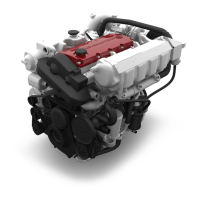
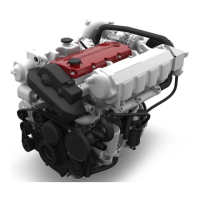
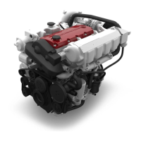
Details various configurations of 4-cylinder marine engines.
Details various configurations of 6-cylinder marine engines.
Detailed technical specifications and an overview for 4-cylinder marine engines.
Detailed technical specifications and an overview for 6-cylinder marine engines.
Details the required diesel fuel specifications for optimal engine performance.
Specifies recommended motor oils, ACEA, API service codes, and SAE viscosity.
Provides a table to diagnose and resolve common engine starting and running issues.
Outlines regular maintenance tasks and their recommended intervals for engine systems.
Explains the functions of the EMS, including efficiency control, self-diagnostics, and data storage.
Describes how the EMS monitors parameters, performs self-diagnostics, and stores error codes.
Provides a step-by-step guide for preserving the engine during extended storage periods.
Details the procedure for breaking in new or rebuilt STEYR diesel engines to ensure performance and longevity.
Provides recommended operating speeds and loads after the engine break-in period.
Emphasizes using genuine STEYR MARINE spare parts to avoid performance loss and ensure quality.
Outlines the minimum requirements for workshops, including training, tools, and spare parts stock.
Defines common terms used in repair procedures.
Lists the measuring units used in the manual according to the International System of Units.
Provides a list of abbreviations used in the manual for clarity.
Lists all operating materials and their order numbers required for engine service.
Provides general safety instructions and highlights potential hazards during repair work.
Offers guidelines to prevent damage during repair works, emphasizing safe handling of materials.
States that the following rules are valid in Austria and local regulations should be followed elsewhere.
Details safety precautions for handling dangerous operating materials and measures in case of fire or spills.
Provides first aid measures for accidents involving operating materials like fuel, lubricants, and battery acid.
Lists specific tightening torques for various engine components like camshaft housing, connecting rods, and main bearings.
Specifies the torque and Loctite required for flywheel screws.
Provides torque specifications for vibration damper screws, including oil application.
Details torque and Loctite requirements for the rear ring carrier screw.
Specifies torque values for the camshaft sprocket nut, including degreasing and lubrication instructions.
Provides a table of general tightening torques based on property class and thread size.
Explains the regular testing procedures for torque wrenches to ensure accuracy.
Describes the color penetration test for detecting surface cracks on workpieces.
Discusses the application and types of adhesives and sealing materials used in engine repair.
Provides guidelines on cleanliness, storage, and application procedures for anaerobic sealing materials.
Provides specific adjustment values for engine timing, timing belt tension, and fuel delivery.
| Number of Cylinders | 4 |
|---|---|
| Engine Type | Diesel |
| Cooling System | Liquid-cooled |
| Fuel System | Direct Injection |
| Cylinders | Inline |