Do you have a question about the STEYR MOTORS M0236K42 and is the answer not in the manual?
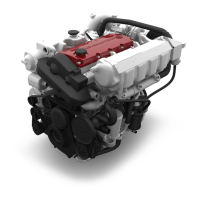
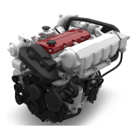
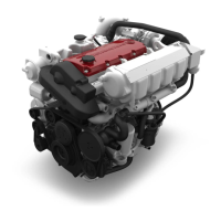
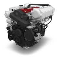
Details on product specifications, illustrations, and technical data for engines.
Outlines warranty terms, dealer obligations, and registration procedures.
Lists major engine components like cylinder block, crankshaft, fuel system, etc.
Details components related to the coupling system.
Lists components of the fuel system, including pump, filter, and injectors.
Covers components of the exhaust system.
Lists components of the cooling system such as coolers, pumps, and pipes.
Details electrical system components like alternator, starter, and wiring.
Covers model summaries, technical specifications, and overviews for engines.
Specifies required fuel quality, cetane number, and other properties.
Provides a chart for diagnosing and resolving common engine symptoms.
Explains the EMS functions and engine power reduction logic.
Emphasizes the use of genuine STEYR MARINE spare parts for optimal performance.
Provides a list of operating materials and their order numbers for engine service.
Highlights general safety knowledge and training requirements for personnel.
Provides specific torque values for various engine components and fasteners.
Provides adjustment specifications for engine timing, belts, and injectors.
Covers procedures for engine timing, locking crankshaft, and replacing mounts.
Details procedures for replacing valves, valve guides, and other cylinder block components.
Outlines procedures for replacing the crankshaft, bearings, and vibration damper.
Covers procedures for replacing the flywheel housing and flywheel.
Details the disassembly of pistons and connecting rods.
Provides steps for removing and replacing the camshaft housing.
Details the procedure for replacing the engine housing, including disassembly steps.
Provides instructions for removing the intercooler and related components.
Covers the removal and installation of the auxiliary drive (PTO).
Details the steps for replacing the engine oil cooler.
Covers the exhaust manifold, seals, and heat exchanger.
Provides procedures for removing and replacing the torsion coupling for different engine types.
Explains the overall function of the fuel system and its components.
Details the disassembly and assembly procedure for the fuel pump.
Outlines the procedure for changing the air filter.
Details the steps for removing and replacing the turbocharger.
Provides instructions for removing the control solenoid.
Explains how to change the fuel filter, including ventilation steps.
Outlines the procedure for replacing glow plugs.
Describes how to measure engine compression pressure using specific tools.
Explains the manual method for testing fuel injection.
Provides steps for disassembling and assembling the hi-riser.
Explains the function and flow of the raw water cooling circuit.
Explains the function and flow of the raw water cooling circuit.
Describes the circulation of coolant in the engine's primary cooling system.
Guides on identifying and diagnosing errors within the cooling system.
Notes that the coolant tank is integrated and not exchangeable in single parts.
Explains how to remove and replace defective coolant pipes and hoses.
Details the steps for removing and replacing the coolant pump.
Provides instructions for exchanging the Poly-V-belt on 4-cylinder engines.
Covers the procedure for exchanging V-belts for alternators and pumps.
Details the steps for exchanging the raw water pump.
Explains how to check the closed cooling system for air and inexplicable coolant loss.
Lists cable numbers and their principal functions in the wiring system.
Explains how to adjust the poly-V-belt tension on 4-cylinder engines.
Provides a troubleshooting chart for starter motor issues.
Specifies battery cable lengths and cross-sections for 4 and 6 cylinder engines.
Explains the EMS functions and engine power reduction conditions.
Identifies the standard instrument panel components and their functions.
Details the removal and checking procedure for the accelerator potentiometer.
Explains the powersupply to the voltage equalizer and battery connection.
Shows the circuit diagram for the DC-DC converter.
Identifies sensor and sender components on a 4-cylinder engine.
Explains how to perform an acid test on the battery to check its condition.
| Brand | STEYR MOTORS |
|---|---|
| Model | M0236K42 |
| Category | Engine |
| Language | English |