INSTALLATION
Preparation
ENGLISH
www.stiebel-eltron.com
DHB-E LCD | 8
Pipe assembly for DHB water plug-in couplings
Use the water plug-in couplings if the existing installation contains
water plug-in connections from a DHB water heater.
Load shedding relay (LR 1-A)
The load shedding relay for installation in the distribution board
provides priority control for the instantaneous water heater when
other appliances, suchas electric storage heaters, are being op-
erated simultaneously.
Central thermostatic valve (ZTA 3/4)
Use the thermostatic valve for central premixing when, forex-
ample, operating an instantaneous water heater with preheated
water. For use in shower operation, the valve must be set to a
maximum of 55°C.
9. Preparation
9.1 Installation location
!
Material losses
Install the appliance in a room free from the risk of frost.
f Always install the appliance vertically and near the draw-off
point. For horizontal installation, see chapter "Alternative in-
stallation methods/ Horizontal installation of the appliance".
The appliance is suitable for undersink and oversink installation.
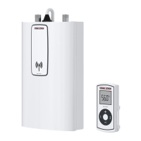
Undersink installation
D0000056242
1
2
1 Cold water inlet
2 DHW outlet
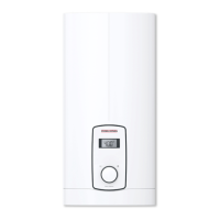
Oversink installation
D0000057030
12
1 Cold water inlet
2 DHW outlet
Note
f Mount the appliance on the wall. The wall must have
sufficient load bearing capacity.
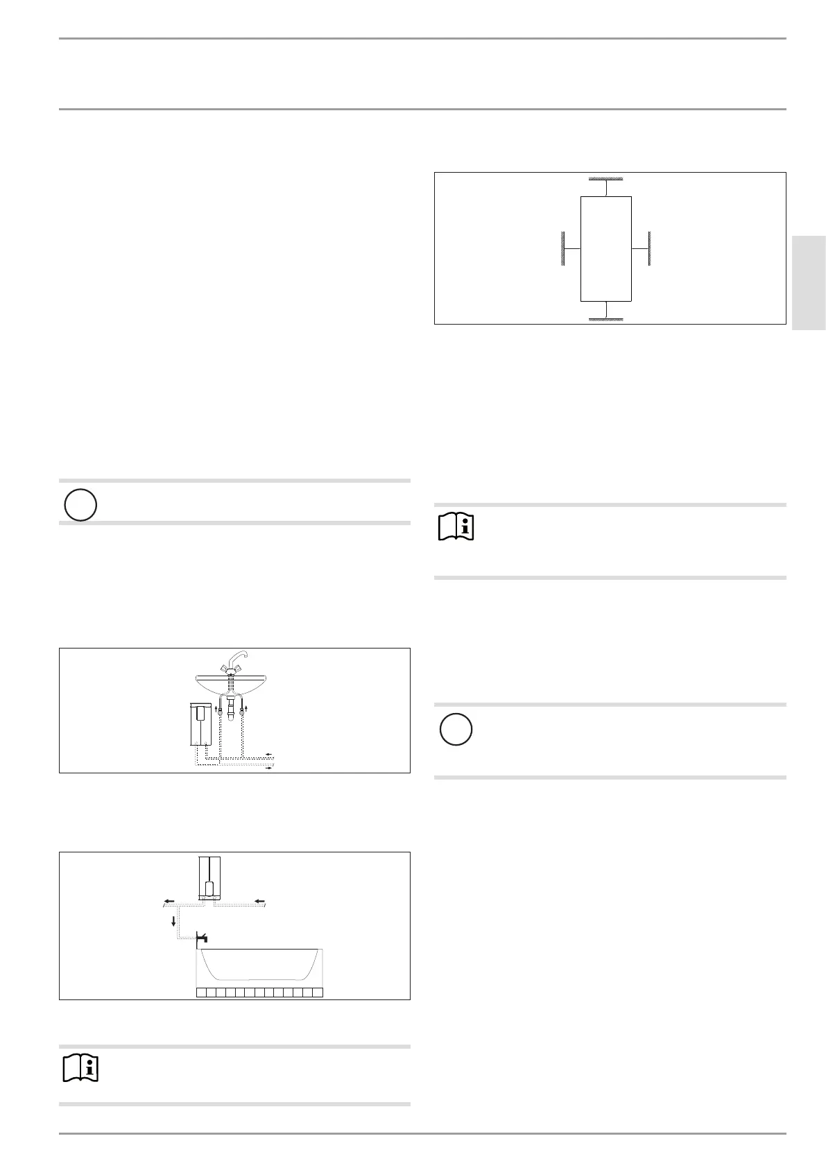
9.2 Minimum clearances
≥50≥50
≥90
≥90
D0000060809
f Maintain the minimum clearances to ensure trouble-free op-
eration of the appliance and facilitate maintenance work.
9.3 Water installation
f Flush the water line thoroughly.
Taps/valves
Use appropriate pressure taps. Open vented taps are not per-
missible.
Note
Never use the 3-way ball shut-off valve in the cold water
inlet to reduce the flow rate. The 3-way ball shut-off valve
is intended only to shut off the cold waterinlet.
Permissible water line materials
- Cold water inlet line:
Pipes made from galvanised steel, stainless steel, copper or
plastic
- DHW outlet line:
Pipes made from stainless steel, copper or plastic
!
Material losses
If plastic pipework systems are used, take into account
the maximum inlet temperature and the maximum per-
missible pressure.
Flow rate
f Ensure that the flow rate for switching on the appliance is
achieved.
f Increase the water line pressure if the required flow rate
is not achieved when the draw-off valve is fully open. If
the flow rate is still not achieved, remove the flow limiter
(see chapter "Installation/ Installation/ Removing the flow
limiter").
 Loading...