Equipment description
The WPAC 1 and WPAC 2 cooling module, in
conjunction with a brine/water heat pump,
enables the demand-dependent cooling of the
living space.
Operate the WPAC 1 exclusively in conjunction
with the Stiebel Eltron brine/water heat
pumps, series WPF 5...13.
Operate the WPAC 2 exclusively in conjunction
with the Stiebel Eltron brine/water heat
pumps, series WPC 5...13.
In conjunction with the WPF/WPC, the WPAC 1/
WPAC 1 offers two output stages:
– passive cooling
– active cooling
Function
The WPAC 1 / WPAC 2 is a module with
integral brine pump 7 (only for WPC 1) and
four diverter valves 8. During the cooling
operation, the valves switch the heating circuit
to the heat pump evaporator and the source
circuit to the heat pump condenser. That way,
the refrigerant circuit can be used to cool the
building; this transfers unwanted heat to the
heat/cooling source.
The cooling module hydraulically connects the
heating circuit with the heat source circuit.
Consequently, the heat source system and the
heating circuit must be filled with a water/
antifreeze mixture (see WPF/WPC installation
instructions).
Never use KKS 30 heat process
medium.
Incorrect operation
Never use this equipment in the open or in
rooms at risk from frost.
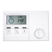
Control:
The cooling module operates automatically
and is regulated by the control unit (WPMi)
of the WPF/WPC. At the WPMi, select the
parameters in line with the heating system
under parameter 6 "Cooling mode" (see
WPF/WPC installation instructions). To allow
the WPMi to enable the cooling mode, connect
the FE 7 or FEK remote control units to the
WPF/WPC.
Maintenance and cleaning
The cooling module requires no maintenance
or cleaning.
Standard delivery
Cooling module WPAC 1
1 x drilling template
4 x pressure hoses
1 x connecting cable 4 x 0.75 mm² (2 m long)
Standard delivery
Cooling module WPAC 1
Symbols used in these instructions
Observe the following safety instructions:
Caution: Warning about possible
dangers.
Note: Important information.
Installation instructions
Positioning, installation and commissioning
must be carried out by trained contractors in
accordance with these installation instructions.
Subject to the relevant system, also observe
the operating and installation instructions
of the components of which the system
comprises.
Hinweis: Keep these operating and in-
stallation instructions safely and pass
them on to any new user, should the equip-
ment change hands, and let your contractor
check their content in conjunction with any
maintenance and repair work.
3 4 2
9
10
8
M5.2
8
M5.1
6
8
M5.4
8
M5.3
3 4 2 1
1
1 2 3 4
6
5
9
7
10
8
M5.1
8
M5.2
8
M5.3
8
M5.4
1 2 3 4
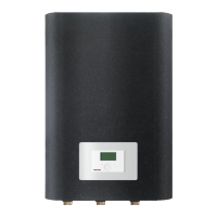
WPAC 1
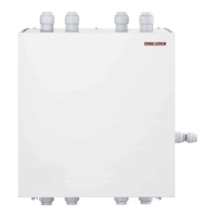
WPAC 2
C26_03_01_0751 C26_03_01_0617
Installation instructions for contractors
1 Brine outlet
2 Brine inlet
3 Heating flow
4 Heating return
5 DHW return
6 Sensor well for
heat pump flow
sensor
7 Brine circulation pump
8 Diverter valve
9 Terminal box
10 Electrical cable
grommets
Equipment layout
 Loading...