This document describes the operation and installation of the Stiebel Eltron HM(S) and HM(S) Trend hydraulic modules for heat pumps.
Function Description
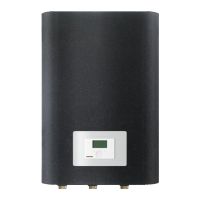
The hydraulic module is designed for air/water heat pumps installed outdoors and is mounted by wall mounting inside the thermal envelope of a building. It provides connections for the heat pump flow, the heating system flow, and the heat exchanger for domestic hot water (DHW) heating. An additional connection is available for the drain hose from the safety valve.
Integrated components include:
- A diaphragm expansion vessel with a 24-litre capacity.
- A high-efficiency (HE) heating circuit pump, sized according to heating output.
- An electric emergency/booster heater.
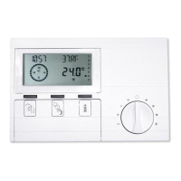
- A WPM heat pump manager.
The WPM heat pump manager controls and regulates the heat pump processes.
Particular feature of the HM(S) with ASL-HM:
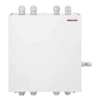
The ASL-HM connector block includes additional connections for the heat pump return, the heating system return, and the return from the DHW heat exchanger. These connections are equipped with ball shut-off valves to simplify installation.
The appliance can be operated with the following air/water heat pumps:
- HPA-0 3-8 CS Plus
- HPA-0 7-13 (C)(S) Premium
- WPL 13/18 E, WPL 13/18 cool
- WPL 15-25 A(C)(S)
- WPL 33 HT(S)
- WPL 07-17 ACS classic
- WPL 19-24 I, A
Electric Emergency/Booster Heater Function:
- Monoenergetic operation: If the heat pump falls below the dual mode point, the electric emergency/booster heater ensures both heating operation and the delivery of high DHW temperatures.
- Emergency mode: If the heat pump malfunctions and cannot operate, the heating output is covered by the electric emergency/booster heater.
Important Technical Specifications
Dimensions and Connections (without ASL-HM):
- Height: 896 mm
- Width: 588 mm
- Depth: 405 mm
- Connections: Heat pump flow (G1 female thread), Heat exchanger flow (G1 female thread), Heating flow (G1 female thread).
- Safety valve drain: c12
Dimensions and Connections (with ASL-HM):
- Height: 1131 mm (including connector block)
- Width: 590 mm
- Depth: 405 mm
- Connections: Heat pump flow (28 mm diameter), Heat pump return (28 mm diameter), Heat exchanger flow (28 mm diameter), Heat exchanger return (28 mm diameter), Heating flow (28 mm diameter), Heating return (28 mm diameter).
- Safety valve drain: c12
Weights:
- HM: 45 kg
- HM Trend: 27 kg
- HMS: 45 kg
- HMS Trend: 27 kg
Power Consumption (Emergency/Booster Heater):
- HM / HM Trend: 8.8 kW
- HMS / HMS Trend: 5.9 kW
Application Limits:
- Max. permissible pressure: 0.3 MPa
- Min. application limit on the heating side: 7 °C
- Max. cooling application limit on the heating side: 70 °C
Hydraulic Data:
- External available pressure differential at 1.5 m³/h: 661 hPa
- External available pressure differential at 2.5 m³/h: 300 hPa
- External available pressure differential at 2 m³/h: 468 hPa
Electrical Data:
- Frequency: 50 Hz
- Rated voltage, control unit: 230 V
- Rated voltage, emergency/booster heater: 400 V (HM/HM Trend), 230 V (HMS/HMS Trend)
- Control unit phases: 1/N/PE
- Emergency/booster heater phases: 3/N/PE (HM/HM Trend), 2/N/PE (HMS/HMS Trend)
- Control unit fuse protection: 1 x B 16 A
- Fuse protection, emergency/booster heater: 3 x B 16 A (HM/HM Trend), 2 x B 16 A (HMS/HMS Trend)
- Power consumption, circulation pump: 3-76 W
Circulation Pump Type:
- Yonos PARA 25/7.5, high-efficiency circulation pump.
IP Rating:
Heating Water Quality Requirements:
- Water hardness: ≤3 °dH
- pH value (with aluminium fittings): 8.0-8.5
- pH value (without aluminium fittings): 8.0-10.0
- Conductivity (softening): <1000 µS/cm
- Conductivity (desalination): 20-100 µS/cm
- Chloride: <30 mg/l
- Oxygen 8-12 weeks after filling (softening): <0.02 mg/l
- Oxygen 8-12 weeks after filling (desalination): <0.1 mg/l
Expansion Vessel Volume:
Usage Features
- Safety: The appliance can be used by children aged 8 and older and persons with reduced physical, sensory or mental capabilities or a lack of experience and know-how, provided they are supervised or instructed on safe use and understand the risks. Children must not play with or clean the appliance unless supervised.
- Permanent Connection: Connection to the power supply must be permanent, with an isolator that disconnects all poles with at least 3 mm contact separation.
- Installation Location: The appliance should be installed close to the heat pump. The wall structure must be able to bear the appliance's weight, and the wall must be even to ensure the appliance cap seals without gaps. Spacer discs can be used for unevenness.
- Filling the System: The heating system should be filled at a low flow rate to prevent damage. The diverter valve of the multifunction assembly (MFG) is centrally positioned for even filling of heating and DHW circuits. The fill pressure should be at least 1.8 bar (pre-charge pressure + 0.3 bar), observing the safety valve's response pressure of 3 bar. If the height difference between the highest point of the heating system and the diaphragm expansion vessel exceeds 13 m, the pre-charge pressure needs adjustment.
- Venting: The pipework can be vented by pulling up the red cap on the air vent valve of the MFG. For ASL-HM models, the heating circuit can be vented at the connector block.
- Sensor Installation: An additional return sensor may be required for certain heat pump types, especially with a buffer cylinder. For heat metering with specific WPL and HPA models, an immersion sensor connected to terminal X61 is used.
- Commissioning: Only a qualified contractor should commission the appliance. All settings at the heat pump manager's commissioning level must be made, and the user instructed. Before commissioning, ensure the heating system is charged, air vent valves are closed, sensors are correctly placed and connected, power supply is correct, and the signal cable to the heat pump is connected.
- High Limit Safety Cut-out: If the heating water temperature exceeds 90 °C, the electric emergency/booster heater shuts down. The cut-out can be reset by pressing a button with a pointed object after resolving the fault.
- Fault Output: For every appliance fault, output X2.10 issues a 230 V signal. For temporary faults, the signal is switched through for a specific time; for permanent shutdowns, it switches through permanently.
Maintenance Features
- Regular Inspection: Regular inspection is recommended to assess the system's current condition.
- Qualified Contractor: Maintenance, including electrical safety checks, should only be performed by a qualified contractor.
- Cleaning: Plastic parts can be cleaned with a damp cloth. Abrasive or corrosive cleaning agents should not be used.
- Original Spare Parts: Trouble-free function and operational reliability are guaranteed only when original accessories and spare parts are used.
- Power Isolation: Before any work on the appliance, it must be isolated from the power supply at the control panel.
- Casing Closure: For safety reasons and to prevent temperature drops below the dew point, the appliance should only be operated with the casing closed and undamaged.
- Diverter Valve Position: If filling or draining the system, the diverter valve should first be placed in its centre position via controller parameter DRAIN HYD in the DIAGNOSIS / RELAY TEST SYSTEM menu.