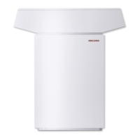
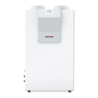
INSTALLATION
Installation
12 | WPL 10 AC | WPL 10 ACS www.stiebel-eltron.com
10.5.2 Venting the heating system
Vent the pipework carefully. For this, also activate the air
vent valve integrated into the heating flow inside the heat
pump.
10.6 Minimum flow rate
For heating operation without buffer cylinder, ensure the mini-
mum flow rate and the availability of defrost energy.
10.7 Setting the flow rate on the heating side
Note
In combination with an hydraulic module or integral cyl-
inder, the flow rate can be checked and set at the heat
pump manager. Observe that the flow rate is set indirectly
via the rating of the pump used.
Check the flow rate in the heat pump manager menu
"INFO / HEATING / FLOW RATE" or "INFO / DHW /
FLOW RATE".
Set the flow rate in the heat pump manager menu
"COMMISSIONING / HEATING / HEATING CIRC PUMP
RATE" or "COMMISSIONING / DHW / DHW PUMP
RATE".
The appliance is designed in such a way that no buffer cylinder
is required to provide hydraulic separation of the flow in the heat
pump circuit and the heating circuit in conjunction with panel
heating systems.
We recommend the use of a buffer cylinder for installations with
several heating circuits.
The minimum flow rate is set via the temperature differential of
the heating system.
Set the heating circuit pump so that the value is equal to or lower
than the maximum temperature differential.
The setting is made in heat pump mode. For this, make the fol-
lowing settings first:
Temporarily remove the fuse from the electric emergency/
booster heater to isolate the emergency/booster heater from
the power supply. Alternatively, switch OFF the second heat
generator.
Operate the appliance in heating mode.
10.7.1 Minimum flow rate with individual room controller by
means of FEK / FE7 in systems without buffer cylinder
Maximum temperature differential on the heating side with indi-
vidual room controller and external programming unit:
0
2
4
6
8
10
12
-15 -10 -5 0 5 10 15 20 25 30
D0000063627
1
1 Minimum flow rate
X Outside temperature [°C]
Y Maximum temperature differential [K]
In the case of systems without buffer cylinder, in menu "SET-
TINGS/ HEATING/ STANDARD SETTINGS", set parameter "BUFFER
OPERATION" to "OFF".
In such cases, one or more heating circuits in the heating system
must be left open. Ensure the minimum flow rate (see "Techni-
cal Data / Data table") by means of the correspondingly opened
heating circuits (see table "Design recommendation for underfloor
heating system inside the lead room").
Design recommendation for underfloor heating system inside the lead room:
Minimum flow
rate
Minimum water content of buffer
cylinder or open circuits
Composite pipework 16 x 2mm/
routing gap 10cm
Composite pipework 20 x 2.25mm/
routing gap 15cm
Lead room
floor area
Number of cir-
cuits
Lead room
floor area
Number of cir-
cuits
l/h l m² n x m m² n x m
WPL 10 AC 700 19 21 3x70 21 2x70
WPL 10 ACS 700 19 21 3x70 21 2x70
Buffer cylinder always
required
Recommended buffer cylinder
volume, underfloor heating
Recommended buffer cylinder
volume, radiators
enable booster heater
WPL 10 AC no 100 200 Yes
WPL 10 ACS no 100 200 Yes

 Loading...


