INSTALLATION
Power supply
www.stiebel-eltron.com WPL 10 AC | WPL 10 ACS | 17
Connection example
BUS H
BUS L
BUS -
L N PE L L N PE L N PE 1 2 3
WP DHC
K1
L N PE
T
1 2 3 4 5 6 7 8 9 10 11 12 13 14 15 16
N 1 2 3 4 5 6 7 8 9 10 11 12 13 14 15 16 PE
Netz N
Netz L
Netz L´
Pumpen L
UP-WP 1
UP-WP 2
UP-Quelle
UP-Hzg. 1
UP-Hzg. 2
UP-WWB
UP-Zirkul.
2. WE
2. WE
Mischer+
Mischer-
UP-Sol/Kue
Außen
Vorlauf
Rücklauf
WB Ein
2. WE
Quelle
Mischer
Analog
Fern 1
Fern 3
BUS H
BUS L
BUS -
BUS +
Fühler 1
Fühler 2
1
3
4
2
D0000035461
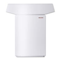
1 Heat pump
2 Heat pump manager
3 Main control panel
4 Power-OFF contactor
11.4 Closing the wiring chamber
1
26�03�01�1759
1 Sound insulation
Position the cover on the appliance.
Secure the cover with the four screws.
Connect the circulation pump for the heat utilisation side to
the heat pump manager in accordance with the technical
guides.

 Loading...


