OpEraTiON
Appliance description
6 | WWK222-302 H www.stiebel-eltron.com
!
Material losses
Operating the appliance outside the application limits
(see chapter "Specification/ Data table") is not permitted.
The appliance may be damaged if operated continuously
outside the application limits.
Note
The appliance is pressurised. During the heat-up process,
expansion water will drip from the safety valve.
If water continues to drip when heating is complet-
ed, please inform your qualified contractor.
2.3 Test symbols
See type plate on the appliance.
3. Appliance description
This appliance enables DHW to be supplied efficiently to several
draw-off points using renewable energy. The appliance extracts
heat from the ambient air. This heat is used, along with additional
electrical energy, to heat up the water in the DHW cylinder. The
amount of electrical energy and time required to heat up the DHW
depend on the temperature of the air drawn in and the tempera-
ture of the water in the cylinder. When the air intake temperature
drops, the heating output of the heat pump is reduced and the
heat-up time is extended.
In the case of indoor installation, the air inside the installation
room can be cooled by 1°C to 3°C due to heat extraction. The
appliance also extracts moisture from the air, which turns into
condensate. The condensate is removed from the appliance via
the condensate drain.
The appliance has an electronic control unit with LC display. The
display shows parameters of interest, such as the top hot water
temperature, mixed hot water volume, etc. It also indicates when
the unit is idle, heating or engaged in defrosting, as well as the
presence of errors and faults. Subject to the power supply and
your draw-off patterns, the water is heated automatically to the
selected set temperature.
External signal transmitters can be integrated via the built-in con-
tact input, e.g. a photovoltaic system to make use of solar power
generated on site.
When a DHW draw-off point is opened, the hot water is pushed
out of the appliance by the inflow of cold water.
The heat pump drive unit is located in the upper section of the
appliance. The DHW cylinder is located in the lower section of the
appliance. To protect against corrosion, the DHW cylinder is coated
internally with special enamel and is additionally equipped with
an impressed current anode.
Available amount of DHW
The appliance's nominal maximum available amount of DHW is
designed for the recommended number of users with average
user behaviour.
3.1 Heat pump operating principle
A closed circuit within the appliance contains refrigerant (see
"Specification/ Data table"). This refrigerant evaporates at low
temperatures. In the evaporator, which extracts heat from the
air drawn in, the refrigerant changes from a liquid into a gas-
eous state. A compressor draws in the gaseous refrigerant and
compresses it. This increase in pressure raises the refrigerant
temperature. This requires electrical energy.
The energy (motor heat) is not lost, but reaches the downstream
condenser together with the compressed refrigerant. There, the
refrigerant transfers heat to the DHW cylinder. An expansion valve
then reduces the still prevalent pressure and the cyclical process
starts again.
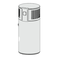
3.2 DHW heating
2
D0000050335
1 Cylinder top sensor
2 Integral sensor
The appliance is equipped with two temperature sensors.
- The cylinder top sensor captures the water temperature in
the upper section of the cylinder.
- The integral sensor is a temperature sensor affixed over the
entire cylinder height. The integral sensor determines the
average cylinder temperature.
The appliance display indicates the temperature in the upper sec-
tion of the cylinder, which is captured by the cylinder top sensor.
The appliance control unit uses the average cylinder temperature
captured by the integral sensor.
DHW heating is started when the available mixed water volume
decreases to the percentage of the maximum mixed water volume
set in the "Charge level" parameter.
The temperature captured by the cylinder top sensor may still
correspond to the set temperature.
 Loading...