66 | WWS 20 www.stiebel-eltron.com
14.6 Data table
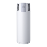
WWS 20
233898
Application limits
Max. DHW temperature with heat pump only °C 60
Max. permissible temperature, DHW °C 60
Min./max. application limits, heat source °C -5/+40
Minimum installation room volume (recirculation
air mode, general domestic use)
m³ 20
Maximum permissible operating pressure, cold
water/DHW
MPa 0.6
Output data
DHW reference temperature (EN 16147) °C 55
Nominal load profile (EN16147) with reference to
300l cylinder
XL
Maximum available amount of DHW at 40 °C (EN
16147 / A15) with reference to 300l cylinder
l 373
Heat-up time (EN 16147 / A15) with reference to
300l cylinder
h 8.30
Average heating output (EN 16147 / A15) with ref-
erence to 300l cylinder
kW 1.9
Average power consumption of heat pump (EN
16147 / A15) with reference to 300l cylinder
kW 0.5
COP (EN 16147 / A15) with reference to 300l cyl-
inder
3.16
Reference DHW cylinder SBB 300 trend
(233490)
Hydraulic reference connection Via inlet pipe
Maximum permissible power consumption of op-
tional electric heater rod
kW 2.0
Electrical data
Power supply 1/N/PE 220-240 V
50 Hz
Average operating current A15/W10-55 A 2.6
Max. starting current A 16.5
Max. power consumption kW 0.75
MCB/fuse rating A C16
Sound emission data
Sound power level without air duct dB(A) 57
Versions
IP rating IP 2X
Refrigerant R134a
Refrigerant charge kg 0.53
Global warming potential of refrigerant (GWP100) kg CO
2
equiv.
1430
CO
2
equivalent (CO
2
e) t 758
Power cable length approx. mm 1600
Hydraulic data
Type internal primary pump 2RS12/2-3 Ku
Max. residual head internal primary pump m 1.1
Water flow rate m³/h 0.4
Inlet pipe pressure drop hPa 16
Dimensions
Height mm 432
Width mm 657
Depth mm 657
Weights
Weight kg 45
WWS 20
Connections
Heat pump connection G 3/4
Condensate connection mm 22
Air duct connector, top mm 160
In the case of hydraulic action via inlet pipe: DHW
connector, cylinder min.
G 1
In the case of hydraulic connection via side inlet
connectors: Inlet connector, cylinder min.
G 1
In the case of hydraulic connection via smooth tube
indirect coil: Heat transfer surface area (per WWS
20), cylinder min.
m²
1.4
Values
Air flow rate, free-blowing m³/h 510
Available external pressure, ventilation Pa 80
Max air duct length 160 mm (including 3 x 90°
bends)
m 20
Reduction max. air duct length per additional 90°
bend
m 2.5
The output data refers to new appliances in factory setting with
clean indirect coils and no connected air ducts.
The output data given refers to the hydraulic connection of the
reference DHW cylinder specified in the data table. If a different
DHW cylinder is used or the hydraulic connection is as described
in chapter "Heating the DHW cylinder via the integral smooth tube
indirect coil", different and possibly lower output and efficiency
data should be expected.
Guarantee
The guarantee conditions of our German companies do not
apply to appliances acquired outside of Germany. In countries
where our subsidiaries sell our products a guarantee can only
be issued by those subsidiaries. Such guarantee is only grant-
ed if the subsidiary has issued its own terms of guarantee. No
other guarantee will be granted.
We shall not provide any guarantee for appliances acquired in
countries where we have no subsidiary to sell our products.
This will not aect warranties issued by any importers.
Environment and recycling
We would ask you to help protect the environment. After use,
dispose of the various materials in accordance with national
regulations.
INSTALLATION | GUARANTEE | ENVIRONMENT AND RECYCLING
Specication
ENVIRONMENT AND RECYCLING
GUARANTEE

 Loading...