ENGLISH
GB
SYMBOLS
The following symbols are displayed on the ma-
chine in order to remind you about the safety pre-
cautions and attention necessary when using the
machine.
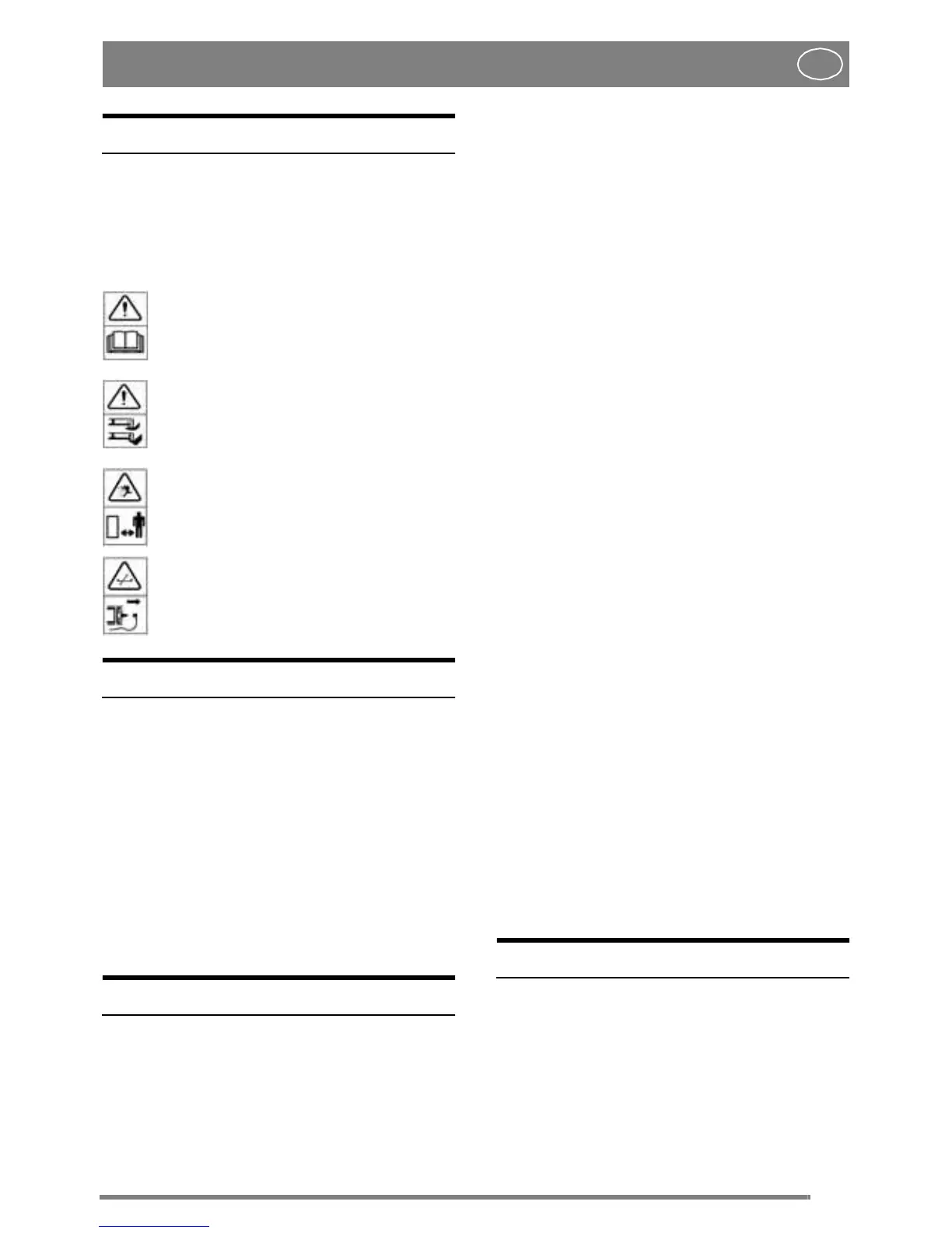
The symbols mean:
Warning!
Read the instruction book and safety man-
ual before using the machine.
Warn ing!
Do not put hands or feet under the cover of
the machine when it is running.
Warn ing!
Beware of objects being flung out. Keep
spectators away.
Beforestarting any repair work, removethe
spark plug cable from the spark plug.
PREPARATION
If this clipping unit is used with the Park model,
the number of revolutions per minute should be re-
duced slightly in order to comply with the current
regulations for approved noise levels:
- Senator and President models: reduce to 3,000
rpm
- Royal, Pro 16, Pro 18 and Pro 20 models: re-
duce to 3,200 rpm
This adjustment torpm should only be made by the
retailer or at anauthorisedworkshop, i.e. bypeople
who have the correct skills and equipment.
ASSEMBLY
MOWER DECK
1. Fit the support wheels and the deflector as show
in figure 1.
2. Fit the attachment brackets D on the front axle
studs by using the washers and locking clips (fig 2).
3. Slide in the attachment's fixing arms into the ma-
chine's attachment brackets.
4. Setthe v-belt on the machine's central belt pulley
F(fig3).
5. The tension roller G should rest on the left-hand
side of the v-belt, seen from the driver's seat (fig 3).
6. Now pull the mower deck forwards so that the
holes in the fixing arms correspond with the holes
on the attachment brackets.
7. Insert the screws and tighten.
8a. Park -1999:
Hook the tension roller spring H into the floor on
the right-hand side (fig 3).
8b. Park 2000-
Hook the tension roller spring H into the fastener,
just behind the front right wheel (fig 3).
9. Lift up the mower deck and hook the chain into
the attachment lifter.
Whenchangingthev-beltordismantlingthemower
deck follow the above procedures in the reverse or-
der.
SETTING
1. Check that the tyres have the correct air pressure.
Front: 0,6 bar (9 psi).
Rear: 0,4 bar (6 psi).
2. To obtain an even cut from the mower deck its
forward and rear edges must be parallel to the
ground.
- Check this by placing the machine on a flat sur-
face.
- If adjustmentis required, adjust using the washers
I at the support wheels (fig 1).
Points 1 and 2 must be carried out for the mower
deck to mow evenly.
USE
MOWING HEIGHT
Themowerdeck has17fixed mowingheights,from
30 mm to 80 mm.
N.B. The stated mowing heights apply when the
machine is standing on firm ground.