WORKSHOP MANUAL
T...102/122 - TC...102/122
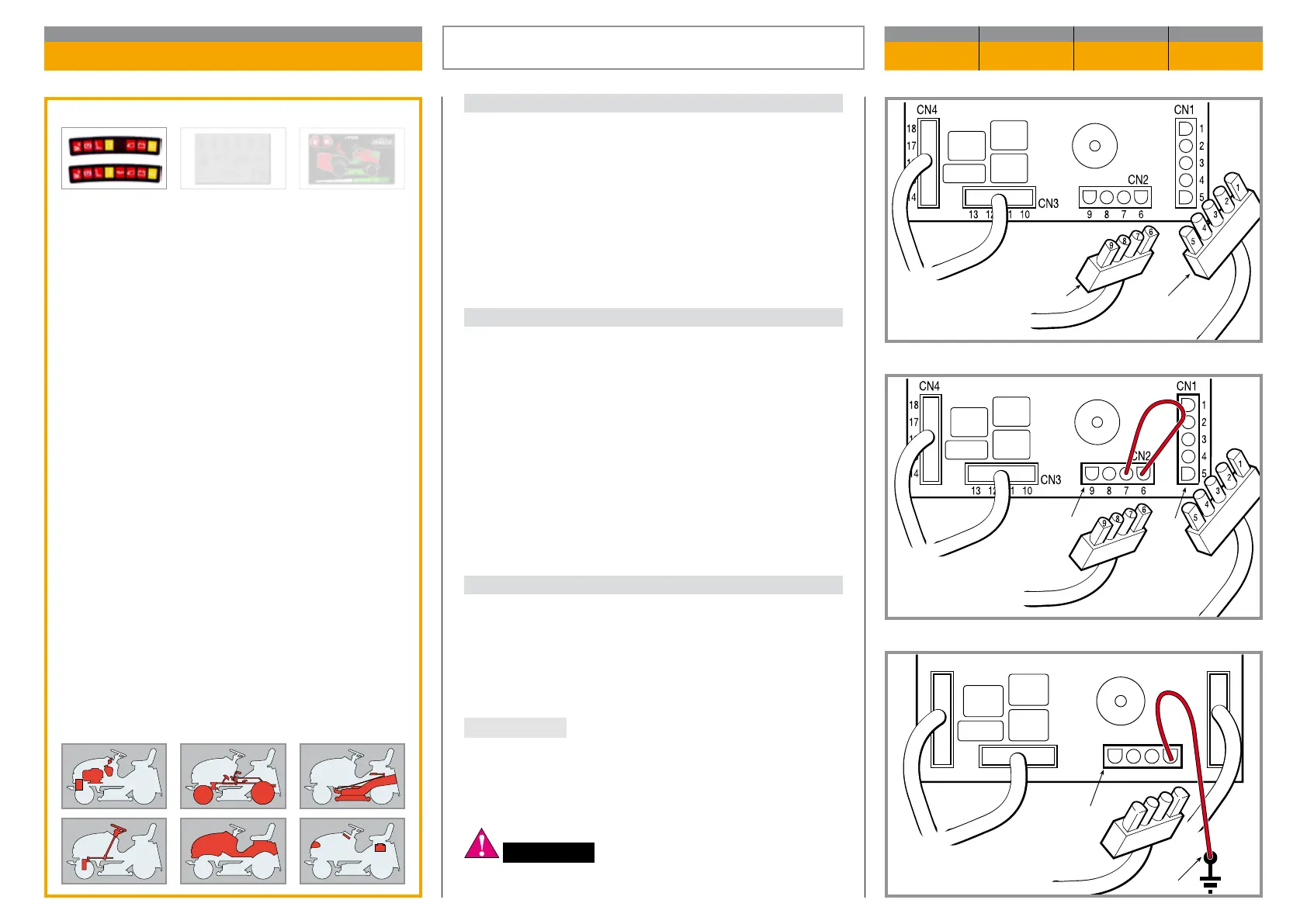
Map of functional units
A) Card power supply
To make this test it is necessary to have:
– The key in the «ON» position
– Connectors CN1 and CN2 disconnected (1)
In this situation all the indicator lights (excluding the
petrol and oil ones – if active) and the battery indica-
tor, if in good charge conditions, should light up.
B) Pilot lamps switch-on test
Making a bridge between the following terminals of
connectors CN1and CN2 of the card (2) should pro-
duce the following eects:
Gr.-catcher warning light = Terminals 6 - 7 o
Seat warning light = Terminals 6 - 3 o
Brake warning light = Terminals 6 - 2 o
Blades warning light = Terminals 6 - 1 o
Fuel warning light = Terminals 6 - 4 on
“Neutral” warning light = Earth - 8 o
C) Self-resetting protection operation check
For this test, put everything in the same situation as
in point «A».
On connecting terminal 6 of connector CN2 of the card
(4) to the frame earth (3), everything should switch o
and the warning buzzer should start o pe rating.
IMPORTANT During this test, the selfsetting protec
tion reaches very high temperatures (around 180 °C)
which are to be considered normal. Similarly, there
might be so me smoke inside the transparent box
which is due to the overheating of the powder inside.
WARNING! Do not touch this component of
the card until it has cooled down.
ELECTRONIC CARD OPERATION CHECK
CHAPTER REVISION FROM ... PAGE
7.8 0 2018 1 of 1
CN4
18
17
16
15
14
1
2
3
4
5
13 12 11 10 9 8 7 6
CN3
CN2
CN1
8
7
9
6
Validity
General informations
Related topics
---
 Loading...