•
Examine brake drum (1) and fan-
wheel (2), replace if necessary -
see 5.4.
Note: If brake drum has to be re-
placed, also check the brake band
- see 8.1
- If brake drum is still serviceable,
clean and roughen its friction
face with emery paper or cloth
(grain size approx. 120
µ
m).
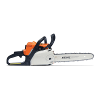
•
Inspect the rotor core assembly
(1) for damage and replace the
rotor if necessary. The fanwheel
and ball bearing have to be remo-
ved for this purpose - see 5.4
and 5.3.
•
Inspect the commutator (2).
Note: In case of minor running
marks, dress the commutator
with emery cloth. If running
marks are severe, fit new rotor.
•
Examine ball bearing (3) and
replace if necessary - see 5.3.
Install in the reverse sequence.
- Clean thread of slotted nut and
rotor stub with standard commer-
cial, solvent-based degreasant
containing no chlorinated or
halogenated hydrocarbons -
see 10.2.
- Coat thread of slotted nut with
Loctite, see 10.2, and screw
slotted nut into pinion.
•
Hold pinion steady and tighten
down slotted nut to 8.0 Nm
(5.9 lbf.ft).
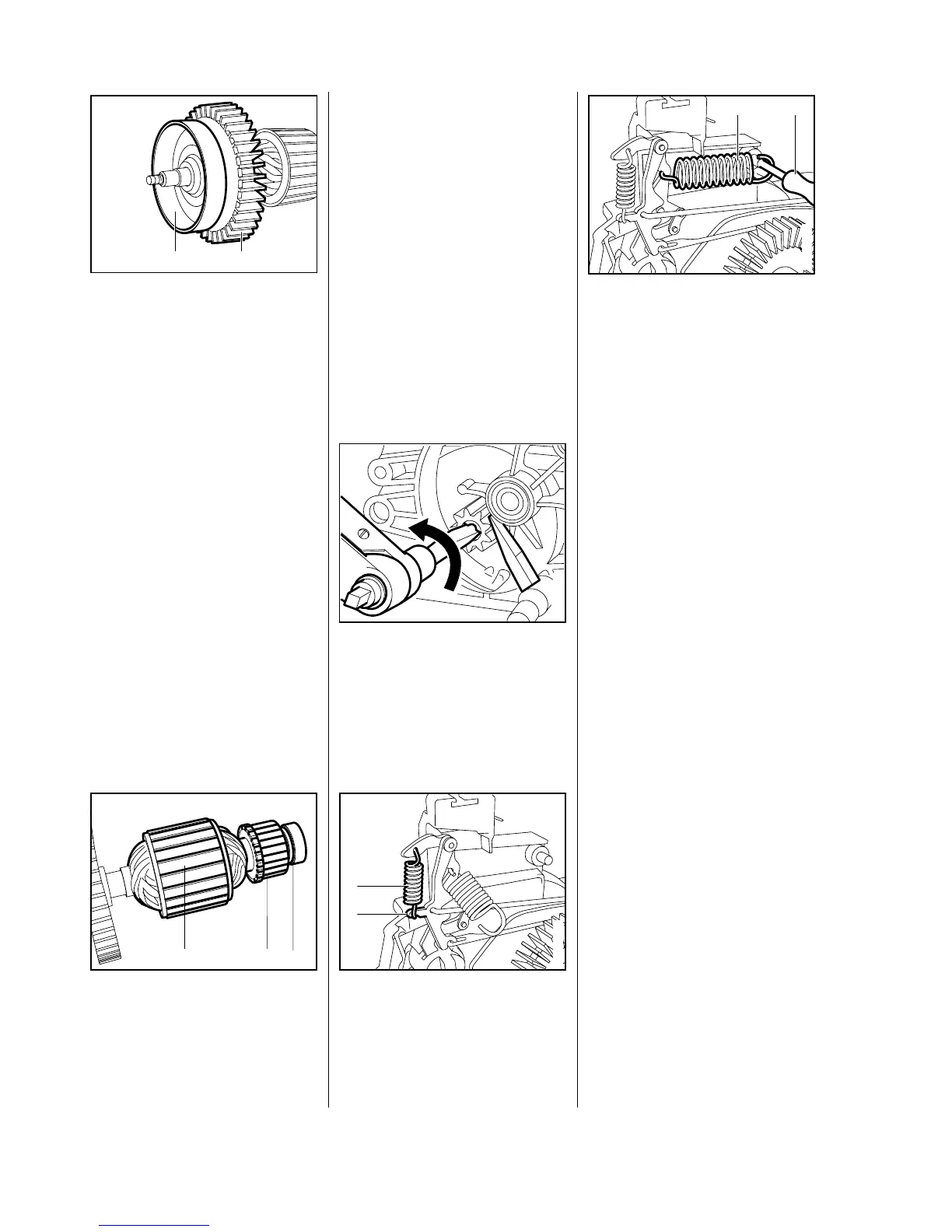
•
Attach smaller spring (1) to
brake lever (2).
•
Use assembly tube (2) 1117 890
0900 to hook larger spring (1) to
pivot pin.
- Torque down gear housing
screws to 3.0 Nm (2.2 lbf.ft) and
screw on hand guard to 4.5 Nm
(3.3 lbf.ft).
VA
2
1
100RA040
VA
100RA039
1 2
VA
100RA041
1
2
3
100RA043
VA
1 2
VA
100RA042
12
 Loading...