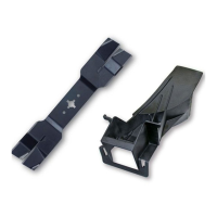
► Place the thrust plate (8) on the shaft (1) so
that its smaller diameter faces up.
► Place the metal cutting attachment (7) on the
thrust plate (8).
► Place the thrust washer (6) on the metal cut‐
ting attachment (7) so that its convex side
faces up.
► Place the rider plate (5) on the thrust washer
(6) so that its closed side faces up.
► Insert the stop pin (9) in the bore up to the limit
stop and hold it depressed.
► Rotate the metal cutting attachment (7) coun‐
terclockwise until the stop pin (9) engages in
position.
The shaft (1) is now blocked.
► Fit the nut (4) counterclockwise and tighten it
down firmly.
► Remove the stop pin (9).
6.3.2 Removing the Metal Cutting Attach‐
ment
► Shut off the engine.
► Insert the stop pin in the bore as far as stop
and hold it depressed.
► Rotate the metal cutting attachment clockwise
until the stop pin engages in position.
The shaft is now blocked.
► Unscrew the mounting nut clockwise.
► Remove stop pin.
► Remove the rider plate, thrust washer, metal
cutting attachment and thrust plate.
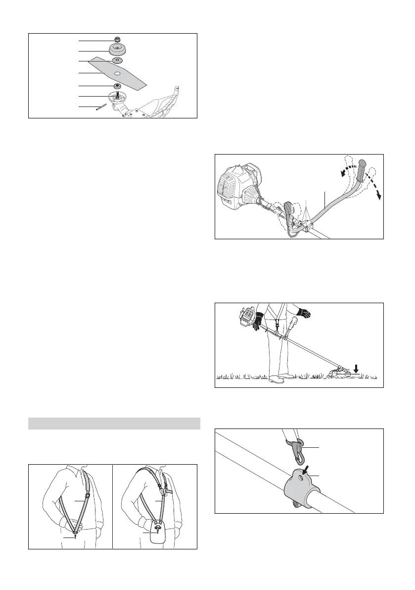
7 Adjusting Trimmer for User
7.1 Fitting and Adjusting the Carry‐
ing System
► Put on the shoulder strap (1) or full harness
(3).
► Adjust the shoulder strap (1) or full harness (3)
so that the carabiner (2) is about a hand’s
width below your right hip.
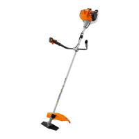
7.2 Adjusting the Bike Handle
The bike handle can be set to different positions
to suit the height and reach of the user.
► Shut off the engine.
► Hook the brushcutter from the carrying ring
into the carabiner of the carrying system.
► Undo the screws (1).
► Swing the bike handle (2) to the required posi‐
tion.
► Tighten down the screws (1) firmly.
7.3 Balancing the Trimmer
The cutting attachment should rest lightly on the
ground.
► Shut off the engine.
► Connect the carrying ring (2) to the carabi‐
ner (1).
► Wait for the trimmer to stop swinging.
7 Adjusting Trimmer for User English
0458-733-0121-C 11
 Loading...