1 Filter cover
Covers the air filter.
2 Air filter
The air filter filters the air entering the engine.
3 Choke lever
The choke lever helps start the engine.
4 Manual fuel pump
The manual fuel pump makes it easier to start
the engine.
5 Spark plug boot
Connects the ignition lead to the spark plug.
6 Spark plug
Ignites the fuel-air mixture in the engine.
7 Muffler
Reduces brushcutter noise emissions.
8 Starter grip
The starter grip is used for starting the
engine.
9 Carburetor adjusting screws
For tuning the carburetor.
10 Fuel tank cap
The fuel tank cap closes the fuel tank.
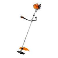
11 Handle
The handle is for holding and controlling the
brushcutter.
12 Throttle cable
Connects the throttle trigger to the engine.
13 Control handle
The control handle is used for operating,
holding and controlling the brushcutter.
14 Slide control
Slide control is used to start, operate and stop
the engine.
15 Throttle trigger lockout
The throttle trigger lockout unlocks the throttle
trigger.
16 Throttle trigger
The throttle trigger is used to control the
engine speed.
17 Shaft
The shaft connects all components.
18 Carrying ring
The carrying ring is for attaching the carrying
system.
19 Handlebar clamp
The handlebar clamp connects the handlebar
to the shaft.
20 Handlebar
The handlebar connects the control handle
and handle with the shaft.
21 Deflector for metal cutting attachments
The deflector for metal cutting attachments
protects the user from flying debris and con‐
tact with the metal cutting attachment.
22 Grass cutting blade
The grass cutting blade cuts grass and
weeds.
23 Gear housing
The gear housing encloses the gearbox.
24 Screw plug
The screw plug closes the filler opening for
STIHL gear grease.
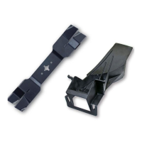
25 Opening for stop pin
The opening for the stop pin accommodates
the stop pin.
26 Stop pin
The stop pin blocks the shaft while a cutting
attachment is being mounted.
# Rating plate with the machine number
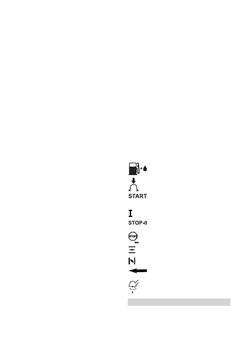
3.2 Symbols
Meanings of symbols that may be on the trimmer
and the deflector:
This symbol denotes the fuel tank.
This symbol denotes the manual fuel
pump.
This symbol denotes the starter grip
and the engine is started with the slide
control in this position.
Engine is operated with the slide control in
this position.
Engine is stopped when the slide con‐
trol is in this position.
Slide control is moved in this direction to
stop the engine.
Engine is started with the choke lever in
this position.
Engine is made ready for start with the
choke lever in this position.
This symbol shows the direction of
rotation of the cutting attachment.
This symbol shows the rated speed of the
cutting attachment.
4 Safety Precautions
4.1 Warning Symbols
Meanings of warning signs on the trimmer:
4 Safety Precautions English
0458-733-0121-C 3
 Loading...