52 MS 231, MS 231 C, MS 251, MS 251 C
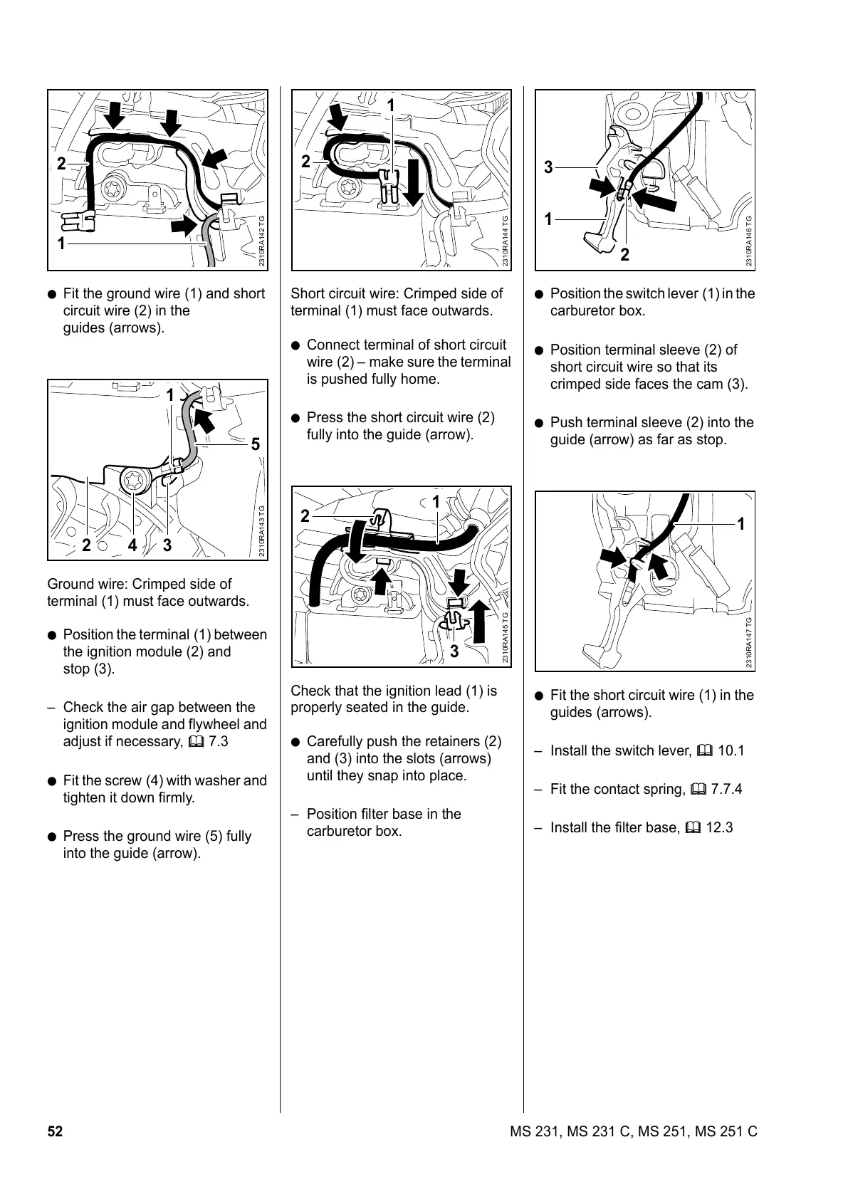
: Fit the ground wire (1) and short
circuit wire (2) in the
guides (arrows).
Ground wire: Crimped side of
terminal (1) must face outwards.
: Position the terminal (1) between
the ignition module (2) and
stop (3).
– Check the air gap between the
ignition module and flywheel and
adjust if necessary, b 7.3
: Fit the screw (4) with washer and
tighten it down firmly.
: Press the ground wire (5) fully
into the guide (arrow).
2310RA142 TG
1
2
2310RA143 TG
42 3
5
1
Short circuit wire: Crimped side of
terminal (1) must face outwards.
: Connect terminal of short circuit
wire (2) – make sure the terminal
is pushed fully home.
: Press the short circuit wire (2)
fully into the guide (arrow).
Check that the ignition lead (1) is
properly seated in the guide.
: Carefully push the retainers (2)
and (3) into the slots (arrows)
until they snap into place.
– Position filter base in the
carburetor box.
2310RA144 TG
1
2
2310RA145 TG
1
3
2
: Position the switch lever (1) in the
carburetor box.
: Position terminal sleeve (2) of
short circuit wire so that its
crimped side faces the cam (3).
: Push terminal sleeve (2) into the
guide (arrow) as far as stop.
: Fit the short circuit wire (1) in the
guides (arrows).
– Install the switch lever, b 10.1
– Fit the contact spring, b 7.7.4
– Install the filter base, b 12.3
2310RA146 TG
1
3
2
2310RA147 TG
1

 Loading...