2
D
S Schlauchschellen (1) an den
Enden mit einer Zange
zusammendrücken und von
den Stutzen an Absperrhahn
und Reduzierstück weg ver-
schieben.
S Halter (2) abnehmen.
S Schlauch (3) zwischen
Brühebehälter und Absperr-
hahn, am Stutzen des
Absperrhahns (4) und Redu-
zierstücks (5) abziehen.
Bei neuen Geräten (Merkmal:
Tank ist auf der Rückenplatte
befestigt):
S Zylinderschrauben (6)
herausdrehen, Anwerfvor-
richtung (7) abnehmen.
S Zündleitungsstecker (8)
abziehen.
S Vier Zylinderschrauben (9)
herausdrehen, Abdeck-
haube (10) abnehmen.
S Kraftstofftank entleeren.
Kraftstoff vorschriftsmäßig
und umweltgerecht entsor-
gen.
S Kraftstoffschlauch (11) am
Winkelstutzen des Vergasers
abziehen.
S Falls vorhanden Schlauch
(12) von der Tanklüftung
abziehen.
S Zwei Schlauchschellen (13)
am Faltenbalg (14) lösen.
S Rückenpolster abziehen oder
Hüftgurt anheben. Befesti-
gungsschrauben (15)
herausdrehen, Motoreinheit
von der Rückenplatte abneh-
men. Faltenbalg (14) gleich-
zeitig von den Stutzen des
Brühebehälters und des
Gebläsegehäuses abziehen.
S Einfüllsieb (16) vom Brühe-
behälter abheben
S Schlauch (17) vom Einfüll-
sieb (16) und vom Reduzier-
stück (18) abziehen.
Hinweis: Der Schlauch (17)
wird an anderer Stelle
weiterverwendet.
Bei älteren Geräten (Merkmal:
Vom Reduzierstück ragt kein
Stutzen zum Anschließen eines
Schlauches nach unten aus
dem Brühebehälter heraus):
G
S Use pliers to open up the
hose clips (1) and slip them
off the stubs on the stop cock
and reducer.
S Remove the retainer (2).
S Disconnect hose (3) between
container and stop cock at
the stop cock (4) and reducer
(5).
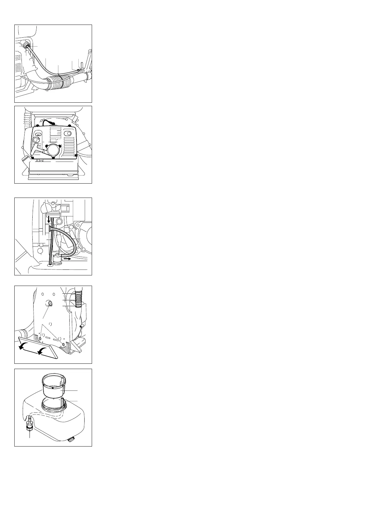
On new machines (tank is
mounted to backplate):
S Take out the screws (6) and
remove the rewind starter (7).
S Pull off the spark plug boot
(8).
S Take out the four screws (9)
and remove the shroud (10)
S Drain the fuel tank. Dispose
of fuel properly in accordance
with local regulations.
S Disconnect fuel hose (11)
from carburetor stub.
S Pull hose (12) (if fitted on your
machine) off the tank vent.
S Loosen the two hose clips
(13) on the bellows (14).
S Remove the back padding or
raise the lap belt. Take out the
mounting screws (15). Lift the
powerhead away from the
backplate and pull the bel-
lows (14) off the stubs on the
container and fan housing at
the same time.
S Take the strainer (16) out of
the container's filler opening.
S Pull the hose (17) off the
strainer (16) and the reducer
(18).
Note:
The hose (17) is used again in a
different position.
On older machines (no stub
projects from the bottom of the
container for connecting a
hose):
F
S Comprimer les colliers de
serrage (1) en saisissant les
extrémités avec une pince et
les écarter de l'embout du
robinet d'arrêt et du raccord
réducteur.
S Enlever l’attache (2).
S Débrancher le tuyau (3) entre
le réservoir de liquide et le
robinet d’arrêt, de l'embout
du robinet d’arrêt (4) et du
raccord réducteur (5).
Sur les nouveaux appareils
(marque d’identification : le
réservoir de carburant est fixé
sur la plaque dorsale) :
S Dévisser les vis à tête cylin-
drique (6), enlever le disposi-
tif de lancement (7).
S Débrancher la fiche (8) du
câble d’allumage.
S Dévisser les quatre vis à tête
cylindrique (9), enlever le
capot (10).
S Vider le réservoir de carbu-
rant. Éliminer le carburant
conformément à la réglemen-
tation, en veillant à la protec-
tion de l’environnement.
S Débrancher le tuyau à carbu-
rant (11) du raccord coudé du
carburateur.
S Si un tuyau (12) est monté, le
débrancher du système
d’aération du réservoir de
carburant.
S Défaire les deux colliers de
serrage (13) du soufflet (14).
S Enlever le rembourragedor-
sal ou la ceinture abdomi-
nale. Dévisser les vis defixa-
tion (15), enlever le groupe
moteur de la plaque dorsale.
Débrancher simultanément le
soufflet (14) de l'embout du
réservoir de liquide et du car-
ter de turbine.
S Retirer le tamis de remplis-
sage (16) du réservoir de
liquide.
S Débrancher le tuyau (17) du
tamis de remplissage (16) et
du raccord réducteur (18).
Remarque: Le tuyau (17) sera
réutilisé à un autre endroit.
Sur les anciens appareils
(marque d'identification : aucun
embout ne dépasse en bas du
réservoir de liquide pour
permettre le raccordement d'un
tuyau) :
1
372BB000 KN
2
3
4
5
1
9
8
9
9
10
9
6
6
372BB001 KN
7
6
12
11
372BB002 KN
372BB003 KN
13
14
15
13
372BB004 KN
16
17
18
 Loading...