© 2019 Stinger • www.stingerelectronics.com
Amplier Owner’s Manual
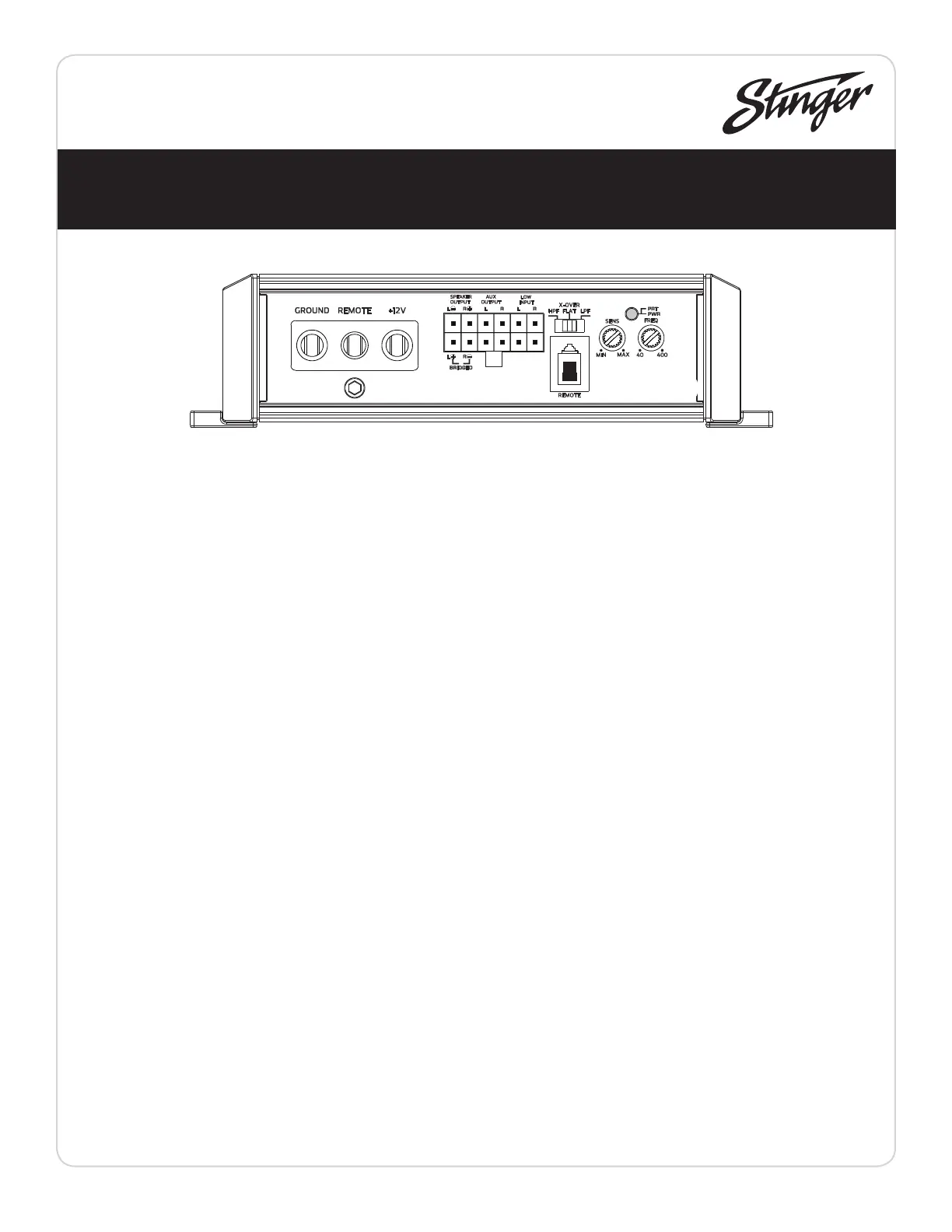
GROUND
Connect to the negative terminal of the
battery or bolted to a clean, unpainted part
of the chassis of the vehicle.
REMOTE
Connected to switched +12V, usually a
remote trigger wire coming from the head unit
or an ignition lead if one is not available.
+12V
Connect to positive terminal (+12V) of the
battery. A in-line fuse should be installed within
18 inches of the battery. A 30 AMP fuse is
recommended for the SPX350X2
Specications
Connections / Settings
SP X350x2
SPEAKER OUTPUT
Used to connect the amplier to speakers.
The SPX350X2 minimum impedance is 2 ohm
Stereo and 4 ohm Bridged. To Bridge the 2
channels, use Left+ and Right-
AUX OUTPUT
Provides a full range signal for an additional
amplier. There is no signal loss if using this
output.
LOW INPUT
Connect preamp signal cables from head unit
to these inputs. For a high-level signal, cut RCA
connectors and connect to speaker wires.
REMOTE LEVEL CONTROL
This port is for connecting the remote
level control knob. This allows up to 20dB of volume
adjustment. Press to Mute.
X-OVER (Crossover)
HPF - FLAT - LPF is selectable. Select FLAT for full range
signal. Select HPF (High Pass Filter) or LPF (Low Pass Filter)
to activate the internal crossover which is continuously
variable from 40Hz to 400Hz using FREQ
SENS
Used to adjust the input sensitivity (Gain) to match
the input level signal. Continuously variable from 0.2V to
10V. Adjust this with the help of a DMM and a test signal
or an Oscilloscope. See System Tuning section for setup
instructions.
FREQ
Used to adjust the crossover frequency when crossover
is set to HPF or LPF. Continuously variable from 40Hz to
400Hz
POWER/PROTECT LED
Amplier status indicator. Blue indicates all systems
working and amplier is on. Red indicates protection
mode, from Thermal Shut Down or Short Circuit (See
Troubleshooting)
SPX350X2
2 Channel Power Amplier