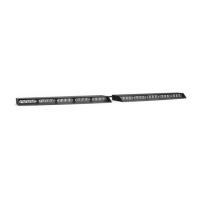
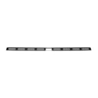
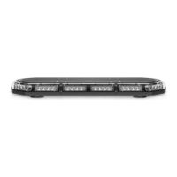
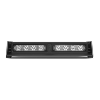
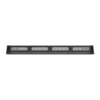
The device described in the manual is the RAPTOR® TIR VISOR LIGHT BAR from SpeedTech Lights. It is a professional-grade emergency warning light bar designed to be mounted on a vehicle's visor.
Function Description:
The RAPTOR® TIR Visor Light Bar is intended to alert pedestrians and other operators to the presence of personnel, emergency vehicles, or an emergency site. It utilizes TIR (Total Internal Reflection) optics and LED diodes to produce various flash patterns for warning signals. The light bar can be controlled via a dedicated switch box (sold separately) or by direct wiring. It features non-volatile memory to recall the last selected flash pattern. The device offers multiple flash modes, including steady burn and random patterns, and can also provide auxiliary functions like "Take Down Steady" and control box backlighting when used with the STL Grand Control Box.
Important Technical Specifications:
- Voltage: 12 VDC
- Amps: < 4.2
- Optic Type: TIR
- LED Count: 48
- Cable Length: 12' Light Bar Cable, 12.5' Power Cable, 12.5' AUX Cable
- Cable Length Between Each Side: 2.5'
- Flash Patterns: 26
- Dimensions: Approximately 18" in length, 5.3" in width, and 1.2" in height (referencing the diagram).
Wiring Diagram Details:
The main power cables are Red (Positive) and Black (Negative).
Control wires (all except Negative contact +12 VDC):
- Yellow: Flash Pattern (cycles through patterns)
- White: Flash Mode 1 (activates warning function in flash pattern memory 1)
- Brown: Flash Mode 2 (activates warning function in flash pattern memory 2, only when Flash Mode 1 cable is receiving +12VDC)
- Blue: No Function
- Green: Take Down Steady
AUX Wiring Diagram (functional with STL Grand Control Box):
- Red: AUX Positive
- Blue: AUX Negative
- White: Control box back light
Usage Features:
- Control Box Operation (Sold Separately):
- Power Button: Turns the Direct Control Box On/Off.
- Mode 1 Button: Activates warning function in flash pattern memory 1.
- Mode 2 Button: Activates warning function in flash pattern memory 2.
- Flash Pattern Button: Cycles through flash patterns. Features non-volatile memory. Shortcuts include holding for 3 seconds for Steady Burn mode and 5 seconds for Random pattern mode.
- TD Button*: (Take Down) 1st press for TD Steady Burn On, 2nd press for TD Off.
- AUX Button*: Toggles power to AUX cables On and Off.
- Night Button**: Activates back light LEDs in the control box. (Can be hardwired to headlight +12VDC line for automation, after which the button ceases to function).
- Mounting: The light bar can be mounted using either the included Q-RVU Universal Bracket or vehicle-specific Q-RVxx brackets (sold separately).
- Rear Track Mounting: Involves sliding Philips pan head screws into the rear track of the unit, aligning forked visor brackets, and securing them with flat washers, split lock washers, and hex nuts. Rubber protective strips are applied to prevent windshield chatter.
- Base Bracket Mounting (Alternate): If direct rear track mounting positions the unit too far from the windshield, base brackets can be used for additional adjustability. This involves attaching base brackets to the unit's bottom, then attaching forked visor brackets to the base brackets.
- Vehicle Specific Brackets: Offer the same mounting versatility as the base bracket method, allowing for lateral and/or forward adjustment.
- Extension Cable (Sold Separately): Available with or without connectors. Installation may involve connecting existing connectors, cutting and soldering wires, or cutting the main cable harness and reattaching connectors. Care must be taken to avoid exposing connections to heat, moisture, or debris.
- Q-RVE Raptor Visor Extender Installation (Sold Separately): Extenders can be installed by aligning the wider side with the Raptor, sliding it over the lip, applying rubber strips, seating the Raptor to the windshield, applying double-sided chatter guard tape, and securing with base screws.
Maintenance Features:
- Daily Inspection: Users are advised to inspect and test the product daily to ensure it operates properly and is mounted correctly.
- Cleaning: Only water (H2O) with a soft cloth should be used to clean the light bar and lenses.
- Avoidance:
- Never take the light bar through a car wash (pressure washers, automatic car washes, brushes, chemicals can scratch or damage the equipment).
- Do not use a pressure washer to clean any STL products.
- Lens Replacement: Yellowing of clear lenses may occur over time; replacement lenses can be purchased by contacting STL Customer Service.
Safety Warnings and Notices:
- This document must be read by the end user and installer.
- STL products are intended for authorized personnel only.
- Users must understand and obey all laws regarding emergency warning devices.
- Never stare directly into the LEDs to prevent eye damage.
- Ensure the visual and audible signal is not blocked by vehicle components or people.
- Test equipment daily for proper function.
- Proper installation and wiring are crucial for effectiveness and safety.
- Avoid live electrical connections; grounding or shorting can cause severe injury or vehicle damage, including fire.
- Mount light bars a minimum of 12"-34" from radio antennas to prevent electromagnetic interference.
- Avoid installing equipment in airbag deployment areas to prevent injury and ensure airbag effectiveness.
- Mount equipment securely according to vehicle manufacturer instructions.
- Bench test all units prior to installation.
- Never cut wires or work on the unit while connected to a power source.
- If drilling is required, ensure no vehicle components are damaged, deburr holes, and use grommets for wire passage.
- Use grommets, cable ties, and looms to anchor and protect wiring.
- Fuses must be properly sized and located, and never use a fuse with a higher amp rating than the initial fuse.
- Insulation displacement connectors are not to be used.
- Ensure a secure electrical connection to the battery's Ground Post (NEGATIVE (-)). Do not use Circuit Breaks.
- Store instruction manuals for future reference.
- Control boxes or remote devices should be installed in a location that allows safe operation without losing eye contact with the roadway.
- Never activate or control equipment in hazardous driving conditions.
- Use SXL type wire in the engine compartment where higher heat resistance is required.
- Failure to follow safety precautions, warnings, notices, and instructions will void the warranty and/or cause serious injury.