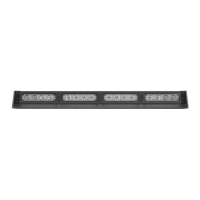
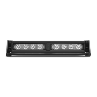
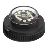
The STRIKER® 4 DASH LIGHT is a warning device designed to alert pedestrians and other operators to the presence of personnel, emergency vehicles, emergency sites, and other warning needs. It is a professional-grade piece of equipment intended for strict use by authorized personnel.
Function Description:
The STRIKER® 4 DASH LIGHT is designed to provide visual warning signals. It features multiple flash patterns and can be synchronized with up to two units. The device operates on 12 VDC and has a low current draw of less than 2.8 Amps. It utilizes TIR (Total Internal Reflection) optics and contains 16 LEDs. The unit comes with an 11-foot light bar cable, and a 1.5-foot cigarette plug cable is sold separately for convenient operation. The cigarette lighter plug switch (sold separately) allows for easy control with an On/Off/On switch to turn the light bar on in Memory Mode 1 (top position) or Memory Mode 2 (bottom position), and off (middle position). A flash pattern button on the cigarette plug cycles through patterns with each press, recalls the last selected pattern via non-volatile memory, and allows toggling between Steady Burn mode (hold for 3 seconds) and Random pattern mode (hold for 5 seconds).
Important Technical Specifications:
- Voltage: 12 VDC
- Amps: < 2.8 A
- Optic: TIR
- LED Count: 16
- Cable Length: 11' Light Bar Cable, 1.5' Cig Plug Cable (Sold Separately)
- Flash Patterns: 26
- Dimensions: Approximately 16.25" (length) x 1.25" (height) x 2.25" (depth)
Wiring Diagram:
The device uses a color-coded wiring system:
- Red*: Positive - Memory Mode 1 (main power cable)
- Black*: Negative (main power cable)
- Yellow: Flash Pattern
- Green*: Positive - Memory Mode 2 (main power cable)
- White: Sync (Max 2 units)
- NOTE: All cables except Negative contact +12 VDC.
Usage Features:
- Flash Pattern Synchronization: To synchronize multiple units, ensure both units are powered on and flashing on the same pattern. Connect the White cables of both units, then connect the Yellow cables of both units to +12 VDC to cycle all units to the next pattern. Power all units off and back on to verify synchronization. It is recommended to connect both units to a single control switch for syncing.
- Non-Volatile Memory: All STL LED products are equipped with non-volatile memory, which recalls the last selected flash pattern when the product is turned on.
- Mounting Options (Sold Separately):
- 90° Suction Cup Bracket: Secures the unit to a surface using rubber suction cups. The bracket attaches to the unit's slide track with screws, nuts, and washers.
- 360° Suction Cup & L-Brackets: Replaces standard end caps with 360° suction cup end caps. Brackets attach to end caps, and suction cups attach to brackets. Can also be used as L-bracket mounts without suction cups.
- Surface Mount End Caps: Replaces standard end caps for surface mounting.
- Headliner Mounting Bracket: Available in static (one solid piece) and adjustable (base bracket and J-bracket) configurations. Attaches to the unit's slide track.
- Static Mounting Bracket: Secures the unit to a surface using screws that align with the bracket oval tracks.
- Windshield Visor Assembly and Mounting: An optional visor can be attached by removing stock end cap screws, securing visor end caps to the visor using short screws, and then securing the visor assembly to the light bar using long screws.
- Extension Cable (Sold Separately): Extension cables are available with or without connectors. If using a cable with connectors, simply plug into the control box. If using a cable without connectors or needing to cut the main cable, wires must be soldered and heat-shrunk, ensuring no cross-connection. Avoid exposing connectors, cables, or solder points to heat, moisture, or debris.
Maintenance Features:
- Cleaning: Use water with a soft cloth to clean the light bar and lenses.
- Avoid Car Washes: Never take the light bar through a car wash, including pressure washers, automatic car washes, or those with brushes or chemicals that could scratch or damage the equipment.
- Daily Inspection: Inspect and test the product daily to ensure it operates properly and is mounted correctly.
- Lens Replacement: Yellowing of clear lenses may occur over time; replacement lenses can be purchased by contacting STL Customer Service.
Safety Precautions:
- Never stare directly into the LEDs.
- Do not cut wires or work on the unit while it is connected to a power source.
- Do not install the product or route wires through or in the airbag deployment area.
- Ensure proper drilling procedures to avoid damaging vehicle components.
- Use grommets in all wire passage holes and anchor all wiring with cable ties and looms.
- Fuses must be properly sized and located as close to the power take-off points as possible. Do not use a fuse with a higher amp rating than the initial fuse provided by STL.
- Do not use insulation displacement connectors or circuit breaks.
- Ensure a secure electrical connection to the battery's Ground Post.
- Install control boxes or remote devices in a location that allows safe operation without obstructing the driver's view.
- Do not activate or control equipment in hazardous driving conditions.
- Use SXL type wire in the engine compartment where higher heat resistance is required.
- All wiring must comply with minimum wire size recommendations and be protected from hot surfaces and moving parts.
- Failure to follow safety precautions, warnings, notices, and instructions may void the warranty and cause serious injury.