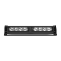
The SpeedTech Lights (STL) STRIKER® 2 DASH LIGHT is a professional-grade emergency warning device designed to alert pedestrians and other operators to the presence of personnel, emergency vehicles, or emergency sites. This instruction manual provides crucial information for proper and safe use, installation, and maintenance of the device.
Function Description
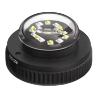
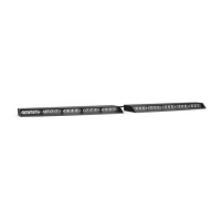
The STRIKER® 2 DASH LIGHT is intended to provide visual warning signals. It features multiple flash patterns and can be synchronized with up to two units. The device operates on a 12 VDC power source and has a low current draw of less than 1.4 Amps. It utilizes TIR (Total Internal Reflection) optics and contains 8 LEDs. The unit comes with an 11-foot light bar cable, and a 1.5-foot cigarette plug cable is sold separately for convenient operation.
The device offers two memory modes for flash patterns, allowing users to quickly switch between preferred settings. It also includes a sync feature to coordinate flash patterns across multiple units.
Important Technical Specifications
- Voltage: 12 VDC
- Amps: < 1.4 Amps
- Optic Type: TIR (Total Internal Reflection)
- LED Count: 8 LEDs
- Cable Length: 11' Light Bar Cable, 1.5' Cig Plug Cable (Sold Separately)
- Flash Patterns: 24 distinct flash patterns
- Synchronization: Supports up to 2 units
- Memory: Non-volatile memory to recall the last selected flash pattern
Usage Features
The STRIKER® 2 DASH LIGHT offers several features to enhance its usability and adaptability:
- Multiple Flash Patterns: Users can cycle through 24 different flash patterns using a dedicated button on the control switch (if using the cigarette lighter plug switch).
- Non-Volatile Memory: The device retains the last selected flash pattern even after being powered off, ensuring consistent operation.
- Flash Pattern Shortcuts:
- Steady Burn Mode: Hold the flash pattern button for 2 seconds to activate Steady Burn mode.
- Random Pattern Mode: Hold the flash pattern button for 4 seconds to activate Random pattern mode.
- Synchronization: Up to two STRIKER® 2 units can be synchronized to flash in unison. To sync, ensure both units are powered on and flashing the same pattern, connect their White sync cables, and then simultaneously trigger the flash pattern changer on both units to cycle to the next pattern. Powering both units off and back on completes the sync process. It is recommended to connect both units to a single control switch for optimal synchronization.
- Cigarette Lighter Plug Switch Operation (Sold Separately): This optional accessory provides convenient control:
- On/Off/On Switch:
- Top On Position: Turns on the Light Bar in Memory Mode 1.
- Off Position: Turns off the Light Bar.
- Bottom On Position: Turns on the Light Bar in Memory Mode 2.
- Flash Pattern Button: Cycles through flash patterns, recalls the last selected pattern via non-volatile memory, and offers shortcuts for Steady Burn and Random patterns.
- Mounting Options (Sold Separately): The STRIKER® 2 offers various mounting solutions to suit different vehicle configurations:
- 90° Suction Cup Bracket: Allows for secure attachment to windshields or other smooth surfaces. The bracket attaches to the unit via slide track screws, nuts, and washers, with rubber suction cups fastened to the bracket.
- 360° Suction Cup & L-Brackets: Provides versatile mounting. The 360° suction cup end caps replace the standard end caps, allowing for suction cup mounting. Alternatively, the L-brackets can be used for permanent mounting by utilizing the oval mounting tracks without the suction cups.
- Surface Mount End Caps: Replaces standard end caps for a flush, surface-mounted installation.
- Headliner Mounting Bracket: Available in two types:
- Static Headliner Bracket: A single solid piece that secures to the unit via slide track screws, nuts, and washers.
- Adjustable Headliner Bracket: Consists of a base bracket and a J-bracket. The base bracket attaches to the J-bracket via long central tracks, and the assembly secures to the unit via slide track screws, nuts, and washers.
- Static Mounting Bracket: Secures to the unit via slide track screws, nuts, and washers for a fixed mounting position.
- Windshield Visor Assembly and Mounting: An optional visor can be attached to the light bar. This involves removing the stock end cap screws, securing two visor end caps onto the visor using short screws, and then attaching the visor assembly to the light bar using long screws. The original end cap screws should be saved to revert to a non-visor configuration if desired.
Maintenance Features
To ensure the longevity and optimal performance of the STRIKER® 2 DASH LIGHT, certain maintenance practices are recommended:
- Cleaning:
- Never take the light bar through a car wash, including pressure washers, automatic car washes, or washes with brushes or chemicals that could scratch or damage the equipment.
- Clean the light bar and lenses using only water and a soft cloth.
- Lens Replacement: Yellowing of clear lenses may occur over time. Replacement lenses can be purchased by contacting STL Customer Service.
- Daily Inspection: Inspect and test the product daily to ensure it operates properly and is mounted correctly.
- Wiring and Mounting: Regularly check all wiring, fuses, and mounting hardware to ensure they are secure and free from damage. Grommets, cable ties, and looms should be used to protect wiring.
- Instruction Manual Storage: Keep the instruction manual in a safe place for future reference, especially for reinstallation or maintenance. Digital copies are also available on the SpeedTech Lights website.
Important Safety Warnings and Notices
Users and installers must read the entire manual before operating any STL product. Failure to follow safety precautions, warnings, notices, and instructions can result in property damage, serious injury, voided warranty, or damage to the product or vehicle.
- Eye Safety: Never stare directly into the LEDs to prevent momentary blindness or eye damage.
- Electrical Safety:
- Never cut wires or work on the unit while it is connected to a power source.
- Ensure secure and good electrical connections, especially to the battery's Ground Post. Connect the unit's ground wire directly to the NEGATIVE (-) battery post. Do not use Circuit Breaks.
- Use properly sized fuses (included by STL) and locate them as close to the power take-off points as possible. Do not use fuses with a higher amp rating than the initial fuse.
- Properly protect and use caution around live electrical connections to prevent high current arcing, which can cause severe personal injury or vehicle damage, including fire.
- Use SXL type wire in the engine compartment where higher heat resistance is required (SAE J-1128 compliant). All wires must conform to minimum wire size recommendations and be protected from hot surfaces and moving parts.
- Installation Safety:
- Installers must have a good understanding of automotive electronic systems and procedures.
- Do not install the product or route wires through or in the deployment area of airbags (SRS) to prevent damage to the airbag, reduced effectiveness, or the unit becoming a projectile. Consult the vehicle's owner's manual for airbag deployment areas.
- If drilling holes, ensure no vehicle components are damaged. Deburr all drilled holes, remove metal remnants, and install grommets in all wire passage holes.
- Mount the equipment securely to a part of the vehicle with sufficient strength to withstand applied forces, following vehicle manufacturer instructions. Permanent mounting is encouraged, as non-permanent methods may detach under aggressive driving conditions.
- Ensure the visual and audible signals are not blocked by vehicle components (e.g., open trunks, visors), other obstructions, or people.
- If a control box or remote device is used, install it in a location that allows safe operation by both the user and the vehicle, without distracting the driver.
- Never activate or control equipment in hazardous driving conditions.
- Electromagnetic Interference (EMI): Mount light bars a minimum of 12" - 34" from the radio antenna. Do not power equipment from the same circuit or share the same grounding circuit with radio communication equipment. Test all vehicle equipment after installation to ensure no interference.
- Pre-Installation Testing: Bench test all units prior to installation by connecting the positive (Red) and negative (Black) cables to a power source. Verify LED diode and module functionality, flash patterns, non-volatile memory, and check for physical damage. Contact Customer Service if any issues arise.
This device is designed for strict use by authorized personnel. Users are responsible for understanding and obeying all applicable city, state, and federal laws and regulations regarding emergency warning devices. SpeedTech Lights, Inc. assumes no liability for loss resulting from the use of this warning device.