4 SpeedTech Lights, Inc © 2019
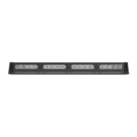
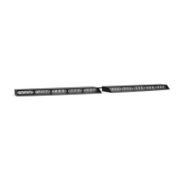
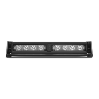
STRIKER
®
2
DASH LIGHT
Specications
Voltage
12 VDC
Amps < 1.4
Optic TIR
LED Count 8
Cable Length 11’ Light Bar Cable, 1.5’ Cig Plug Cable (Sold Separately)
Flash Patterns 24
Wiring Diagram
Wire Color Function
Red*
Positive- Memory Mode 1
Black*
Negative
Yellow
Flash Pattern
Green
*
Positive- Memory Mode 2
White
Sync (Max 2 units)
* Indicates a main power cable. NOTE: All cables except Negative contact +12 VDC.
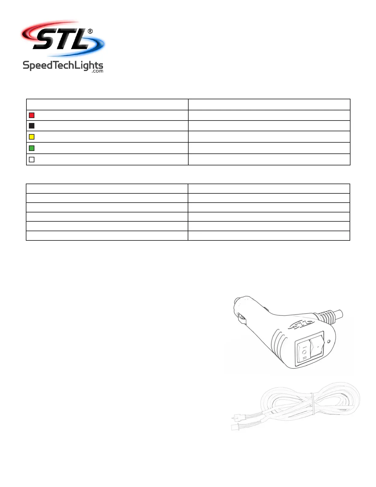
Cigarette Lighter Plug Switch Operation (Sold Separately)
On/O/On Switch:
• Top On Position: Turns on the Light Bar in Memory Mode 1.
• O Position: Turns o the Light Bar.
• Bottom On Position: Turns on the Light Bar in Memory Mode 2.
Flash Pattern Button:
• Cycles to the next ash pattern with each press.
• Non-Volatile memory recalls the last ash pattern selected.
• Hold for 3 seconds to toggle Steady Burn mode.
• Hold for 5 seconds to toggle Random pattern mode.
Extension Cable (Sold Separately)
• If you have an extension cable with connectors, connect the corresponding ends to one
another. Use the connector at the end of the cable to plug into the control box.
• If you have an extension cable with one connector, you will need to cut the connector o
of the main cable harness coming out of the Light Bar. Save it as a spare part. You will
solder and heat shrink each wire within the cable harness to each wire in the extension
cable harness. DO NOT cross connect wires. Use the connector at the end of the
extension cable to plug into the control box.
• If you have an extension cable with no connectors, you will need to cut in the middle
of the main cable harness coming out of the Light Bar. You will solder and heat shrink
each wire within the cable harness to each wire in the extension cable harness. DO
NOT cross connect wires. Use the reattached connector from the end of the main cable
harness to plug into the control box.
• NOTE: DO NOT leave connectors, cables, solder points exposed to heat, moisture, or
debris.
Flash Pattern Synchronization
• Make sure both units that need to be synced together are powered On and ashing on the same pattern.
• Connect the White cables of both units to each other.
• Connect the Yellow cables of both units and contact +12 VDC to cycle all units to the next pattern.
• Power all units O and back On to verify Synchronization is complete.
 Loading...