22
www.stobag.com
A reverser switch, enabling the simultaneous activation of both electric motor phases, must be used for the programming operations.
The special MA 2001 control unit can be used for this purpose. Button ▲ is used to raise the awning; button ▼ is used to lower it. If the move-
ment is reversed, invert the two motor phases.
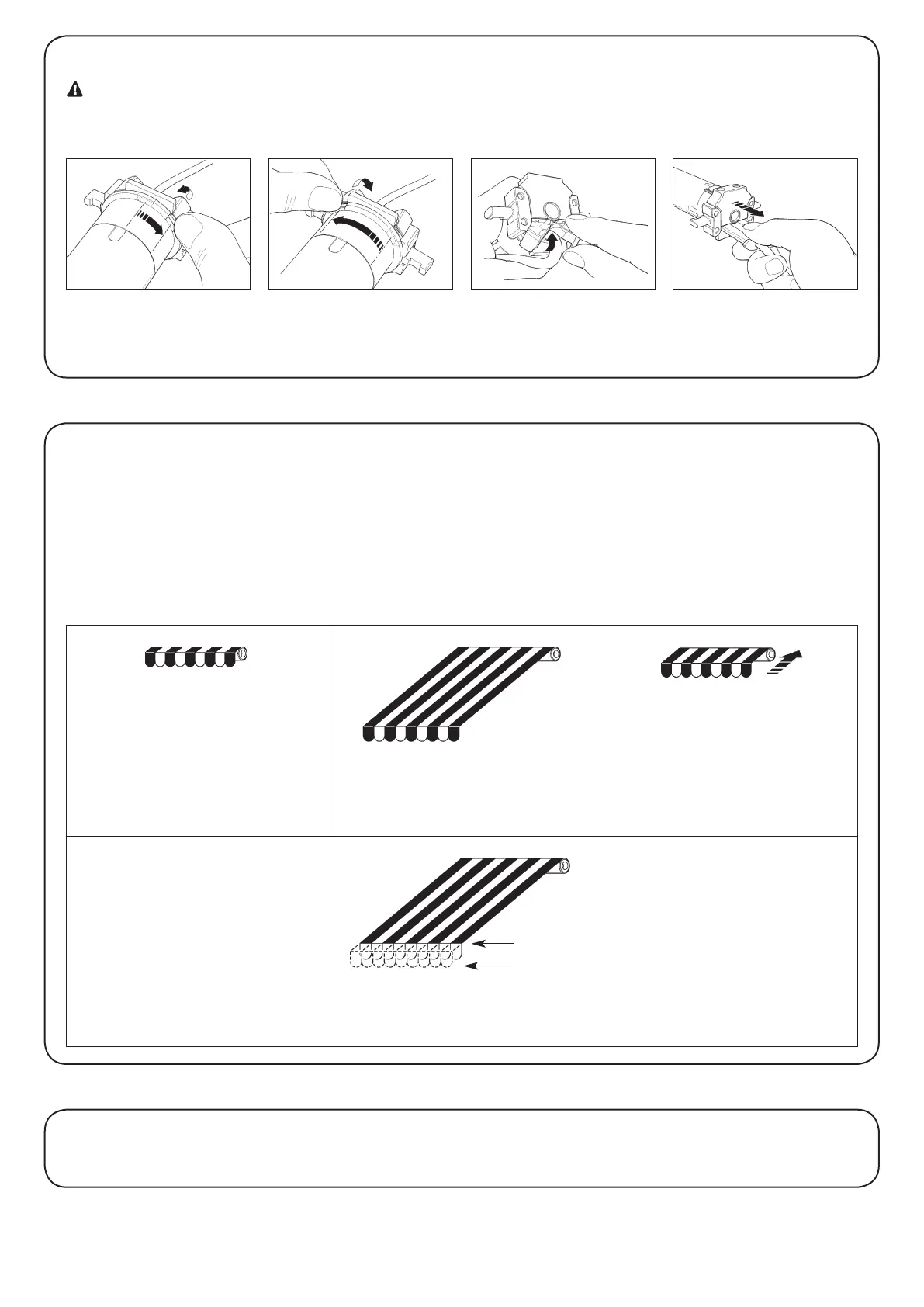
The MOVENO DWIR-E series tubular motors are equipped with an electronic limit switch which interrupts the power supply when the awning
reaches its opening or closing limits, corresponding to the fully rolled up position (0) or fully extended position (1). These two positions must
be programmed into the memory after the motor has been installed and the awning mounted.
The motor can still be controlled even if these two positions, “0” and “1”, have not yet been memorised; however, the movement in this case
will be interrupted momentarily at the start of each manoeuvre and will then continue unimpeded and uncontrolled.
It is also possible to program
• The activation/deactivation of the RDC torque reduction function during the closing operation.
• Position “2” necessary to activate the “FRT” function that allows the fabric to be tightened when the awning is fully open.
Awning closed (position 0) Awning open (position 1)
RDC torque reduction start position for the
closing operation.
Position 2 for “FRT” function
4) Programming
2.3) Connector and power supply cable (This section refers only to the MOVENO-Y version and concerns customer service
personnel only.)
WARNING: if the power cord is damaged it must be replaced with an identical type supplied by the manufacturer or
an authorised customer service centre.
If it is necessary to disconnect the motor from the power supply cable proceed as shown in the figures below:
3) Adjustments
Rotate the lock ring until the
notch matches one of the latch-
on teeth, then release.
Repeat the operation for the oth-
er tooth.
Bend the cable towards the in-
side and remove the protection
by rotating it gently towards the
outside.
Pull out the connector.
“2”
“1”