
 Need help?
Do you have a question about the STORK TRONIC ST552 Glass and is the answer not in the manual?
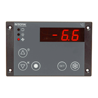
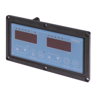
Details on how the device displays temperature and time, including indicator LEDs.
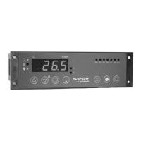
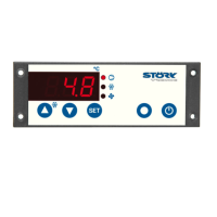
Overview of the device's construction, user interface, and operational modes.
Increases temperature values and adjusts parameters with one-finger setup.
Decreases temperature values and acknowledges system alerts.
Cycles through available temperature setpoints for control operations.
Toggles between slow heating (MELT) and fast heating (TURBO) modes.
Increases time values for timer functions using a one-finger setup.
Decreases time values for timer functions.
Allows selection of specific time values for timer operations.
Starts, stops, or puts the timer and controller into standby mode.
Resets fat operating time records, typically under specific conditions.
Defines reference temperatures and timer values (T1-T5).
Parameters for hysteresis, setpoint limitations, and value correction.
Settings for the Proportional-Integral-Derivative control circuit.
Defines switch-off delay for the heating relay.
Configuration options for display modes, temperature, and time.
Settings for button lock, standby function, and delays.
Configuration for external inputs (E1, E2) and output assignments (K1-K7).
Settings for fan speed, increase, and lead/delay times.
Specific parameters for deep fryer operation like heating clocking.
Parameters related to fat operating time limits and reset options.
Settings for sensor selection, compensation, filter depth, and mains frequency.
Parameters for test heating and temperature limits for special modes.
Illustrates how oil quantity affects heating rate.
Illustrations showing conditions during lack of oil or missing oil.
Explains temperature variations based on sensor placement and design.
Lists parameters H1-H5 relevant for test heating procedures.
Procedure for detecting and handling insufficient oil based on rapid temperature rise.
Procedure for detecting and handling lack of oil based on slow temperature rise.
Notes on reliability and monitoring limitations during baking mode.
Specifies the temperature limit for starting test heating.
Describes alarm indication, acknowledgement, and reset procedures.
Describes the initial slow heating phase and its parameters.
Explains normal heating continuation after minor cooling.
Details slow heating activation after significant cooling below 50°C.
How the controller operates using PID after heating phases.
Describes switching to faster heating (TURBO) via button press.
Describes single-start timer operation and basket activity.
Details multi-start timer operation and basket activity.
Details sensor inputs (Pt100, thermocouple) and measuring ranges.
Specifies external start-stop button and overtemperature signal contacts.
Lists available relay outputs (K1-K7) and their functions.
Describes the PWM output for fan control.
Information on voltage, frequency, and power consumption.
Details on terminal types and cable specifications.
Specifies operating temperature and humidity limits.
The approximate weight of the controller unit.
Details the enclosure's front and rear protection ratings.
Specifies the electrical protection class of the device.
Lists applicable safety and EMC directives.
Information on network interface, cable length, and design.
Requirements for panel installation, including dimensions.
Lists readable actual values from the controller via ST-Bus.
Provides status information words read via ST-Bus.
Details status bits for controller operation and errors.
Describes main flags indicating operational states and events.
 General
| Brand | STORK TRONIC |
|---|---|
| Model | ST552 Glass |
| Category | Controller |
| Language | English |





 To Next Page
