EasyManua.ls Logo

STORK TRONIC ST121-KD1KAR.112 - User Manual

STORK TRONIC ST121-KD1KAR.112
24 pages
Print Icon
To Next Page IconTo Next Page
Loading...
Order number: 900323.001 V1.74 Page 1
© Störk-Tronic 2021 • www.stoerk-tronic.com • Subject to modifications.
Data sheet ST121-KD1KAR.112
1
2
3
F2
PTC
F1
PTC
4
5
A
B
RS485
ST-Bus
230V~
K2K1
1
2
3
4
L1N
K1: 16(6)A 250V~
K2: 16(2,2)A 250V~
Controller for cooling
applications
Order number: 900323.001
As of: 04.11.2021 V1.74
The cooling controller ST121-KD1KAR.112 with two sensor inputs and five keys is used for the thermostatic temperature
control of refrigerating plants. It is supplied with 230V AC and has two exit relays. The functions of the outputs and special
keys can be freely selected, thus various applications with only one controller are possible. The controller, for example, can
operate with two coolers if the evaporator sensor is parametered as sensor for a second refrigerating chamber.
Networking of the controller takes place via the ST-Bus interface.
Sensor: PTC
Range: -50...150 °C
Front size: 120 mm x 42 mm
Panel cut-out: 102.5 mm x 35 mm
Tightness: Front IP65
Connection: screw terminal
Product description
Wiring diagram
Question and Answer IconNeed help?

Do you have a question about the STORK TRONIC ST121-KD1KAR.112 and is the answer not in the manual?

STORK TRONIC ST121-KD1KAR.112 Specifications

General IconGeneral
BrandSTORK TRONIC
ModelST121-KD1KAR.112
CategoryController
LanguageEnglish

Summary

Controller Overview and Wiring

Product Description

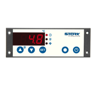
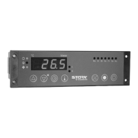
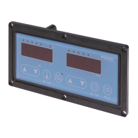
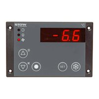
Overview of the ST121-KD1KAR.112 controller's features and applications.

Wiring Diagram

Visual representation of electrical connections for the controller.

General Information and Navigation

Operating Levels Overview

Diagram showing how to navigate through the controller's software menus.

Control Interface and Setup

Control Keys Description

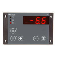
Explains the function of each physical button on the controller.

Parameterisation Process

Outlines the steps and requirements for setting controller parameters.

Parameter Group Navigation

Accessing Parameter Groups

Guide to navigating different parameter categories like Alarms and Network Address.

Parameter List: Alarms (A-)

Alarm Configuration Settings

Details parameters for alarm sensors, limits, hysteresis, and suppression.

Parameter List: Buttons and Inputs (B-)

Key and Input Function Assignment

Configuration of functions for control buttons and external inputs.

Parameter List: Control Circuit 1 (C-)

Circuit 1 Sensor, Setpoint, and Mode

Settings for sensors, setpoints, switching mode, and hysteresis for Control Circuit 1.

Parameter List: Control Circuit 1 (Continued)

Circuit 1 Limits, Protection, and Humidity

Parameters for limits, compressor protection, emergency operation, and humidity control.

Parameter List: Defrosting (D-)

Defrosting Control Settings

Parameters for defrosting interval, mode, temperature, and time limitations.

Parameter List: Fan Control (F-)

Evaporator and Condenser Fan Settings

Configuration of evaporator and condenser fan speeds, modes, and delays.

Parameter List: Temperature Sensors (H-)

Sensor Input Configuration and Calibration

Settings for sensor selection, calibration, filtering, and value display.

Parameter List: Sets, Networking, and Display (J-, L-)

Predefined Sets and Networking

Options for preset data, ST-Bus addressing, and display configurations.

Parameter List: Relays and LEDs (U-)

Relay and LED Function Assignment

Assigning functions to output relays and status LEDs.

Parameter List: Control Circuit 2 (Y-)

Circuit 2 Sensor and Setpoint Configuration

Settings for sensors, setpoints, switching mode, and hysteresis for Control Circuit 2.

Parameter List: Counters and Operating Times (N-, T-)

Counters and Operating Time Tracking

Parameters for monitoring relay switching cycles and operational times.

Master Password and EC Level

Master Password Procedure

Steps to retrieve or reset controller passwords using a master password.

Status Display and Error Messages

Error Code Causes and Remedies

Table listing error messages, their causes, and recommended remedies.

Detailed Parameter Descriptions: Alarms (R-)

Alarm Sensor, Limit, and Relay Settings

In-depth explanation of parameters for alarm sensor assignment, limit values, and relay behavior.

Alarm Suppression and Fault Handling

Detailed descriptions of alarm suppression times, behavior, and fault handling.

Detailed Parameter Descriptions: Control Circuit 1 (C-)

Circuit 1 Sensor, Setpoint, and Mode Details

Detailed explanation of parameters for sensor assignment, setpoints, switching mode, and hysteresis.

Circuit 1 Protection, Emergency, and Humidity

Detailed explanations for compressor protection, emergency operation, and humidity control.

Detailed Parameter Descriptions: Defrosting (D-) and Fan Control (F-)

Defrosting Control Details

In-depth explanations for defrosting interval, mode, temperature, and time limitations.

Fan Control Details

Detailed explanations for evaporator and condenser fan settings, delays, and control.

Detailed Parameter Descriptions: Temperature Sensors (H-) and Fan Control (F-)

Temperature Sensor Details

Detailed explanations for sensor selection, calibration, filtering, and value display.

Fan Control (F-) Details Continued

Further details on fan control parameters like hysteresis and proportional range.

Detailed Parameter Descriptions: Sets, Networking, Display (J-, L-)

Predefined Sets, Networking, and Display Details

Detailed explanations for predefined sets, ST-Bus addressing, and display configurations.

Detailed Parameter Descriptions: Relays, LEDs (U-), and Control Circuit 2 (Y-)

Relay and LED Function Details

Detailed explanations for assigning functions to output relays and status LEDs.

Control Circuit 2 Details

Detailed explanations for Control Circuit 2 sensor, setpoint, and mode settings.

Technical Data

Measuring Inputs and Outputs

Specifications for temperature sensors, relays, and their ratings.

Power Supply, Connectors, and Dimensions

Electrical specifications, connector types, and physical dimensions of the controller.

Related product manuals