EasyManua.ls Logo

STORK TRONIC ST96 Series User Manual

Default Icon
13 pages
To Next Page IconTo Next Page
Page #1 background imageLoading...
Page #1 background image
ST96-32.09
Deep-frying controller
Order number 900087.004
Wiring diagram
Product description
The micro-processed controller ST96-32.09 serves for temperature control at high measuring ac-
curacy and is foreseen for use with deep fryers. The unit has a 3-digit display and is supplied with
230V AC. The controller has an input for Pt100 temperature sensor and one relay exit. The control
setpoints and parameters determining the process are adjusted with a 5-field plastic foil keyboard.
Sensor: Pt100
Range: -99...850
C
Front size: 96mm x 96mm
Panel cut-out: 90.5mm x 90.5mm
Connector: plug and socket
1
Question and Answer IconNeed help?

Do you have a question about the STORK TRONIC ST96 Series and is the answer not in the manual?

STORK TRONIC ST96 Series Specifications

General IconGeneral
BrandSTORK TRONIC
ModelST96 Series
CategoryController
LanguageEnglish

Summary

Product Information

Wiring Diagram

Visual representation of electrical connections for the deep-frying controller.

Product Description

Overview of the controller's capabilities, intended use, and key features.

Controller Features and Operation

Controller Features

Details on the controller's temperature control, display, PID characteristics, and alarm messages.

Controller Operation

Guidance on commissioning, heating with cold/hot fat, and program activation.

Program Management and Status

PID Program Selection and Activation

Steps to select and activate PID programs (Pr.1-Pr.4) for temperature control.

Indicator Lamp Functions

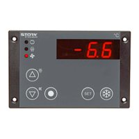
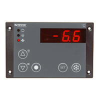
Explanation of the meaning of the status indicator lamps (output, slow heating, quick heating).

Fat Management and Alarms

Details on tracking hot fat operating hours and associated warning/blocking alarms.

Alarm Reset and Switch-off Delay

Internal Alarm and Time Reset

Procedure for resetting internal fat operating time and fat warning messages.

Switch-off Delay Configuration

Setting a switch-off delay for the output relay for specific heating designs.

Heating Control Functions

Heating Phase Control

Explanation of slow heating phases after activation and cooling events.

Manual Heating Intervention

How to switch to normal heating mode manually and undo the change-over.

Control Levels and Parameters

First Control Level: Setpoint Setting

Procedure for viewing and setting the main reference values.

Second Control Level: P Parameters

Accessing and setting control parameters (P1-P28) for PID programs.

Parameter Descriptions

Detailed explanation of each parameter (P1-P28) and their functions.

Third Control Level: A Parameters

Accessing and setting advanced control parameters (A1-A3).

Technical Data

Measuring Input and Outputs

Specifications for resistance thermometer input and relay output.

Power Supply and Connectors

Details on power requirements and connection types.

Ambient Conditions and Enclosure

Operating environment specifications and front panel protection.

Installation Data

Information on front size, panel cut-out, and installation depth.

Related product manuals