1200 Sub-miniature keyboard for public environments
Application / Engineering Manual
This document is provided for use and guidance of engineering personnel engaged in the installation or application of STORM data entry
products manufactured by Keymat Technology Ltd. Please be advised that all information, data, and illustrations contained within this document
remain the exclusive property of Keymat Technology Ltd. and are provided for the express and exclusive use as described above. This
document is not supported by Keymat Technology’s engineering change note, revision or reissue system. Data contained within this document is
subject to periodic revision, reissue or withdrawal. Whilst every effort is made to ensure the information, data and illustrations are correct at the
time of publication, Keymat Technology Ltd. are not responsible for any errors or omissions contained within this document.
1200 Application/Engineering Manual Version 0.99 Nov 2002 Page 7
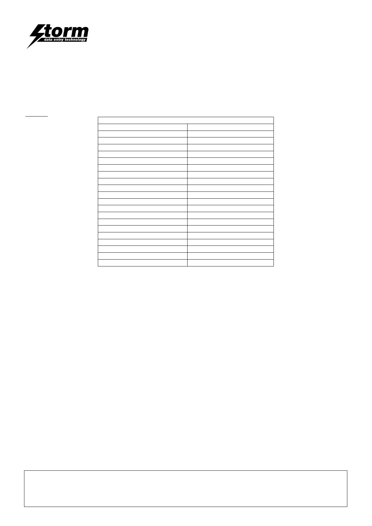
Table 1 below, shows the connector pin designation for the switch circuit matrix.
Please Note: When the keyboard is viewed from the rear, with the connector positioned towards the bottom edge of
the keyboard, pin 1 is on the right, pin 20 is on the left.
Table 1.
Connector pin designator.
Connector Pin Number Row / Column
1 Column 14
2 Column 13
3 Column 12
4 Column 11
5 Column 10
6 Column 9
7 Column 8
8 Column 7
9 Column 6
10 Column 5
11 Column 4
12 Column 3
13 Column 2
14 Column 1
15 Row F
16 Row E
17 Row D
18 Row C
19 Row B
20 Row A
Keytop Layouts are detailed in Appendix 1.
Appendix 3 shows the row and column connection for each switch position. Please note; the characters indicating
row and column connections are not representative of keytop layouts.