
A
Andrea CherryAug 13, 2025
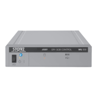
What to do if devices connected with Interface Control or Control do not log on in Storz OR1 SCB CONTROL?
- AAdam HallAug 13, 2025
If the devices connected with Interface Control or Control do not log on, it might be due to several reasons. Check if the RS232 cable is connected to the correct RS232 socket of the Interface Control or ACC Control; if not, use the correct RS232 socket. An incompatible software in the external device could also be the cause, in this case, have the software installed by the manufacturer. Finally, the RS232 cable itself might be incorrect or faulty, try replacing or inserting the cable.