©Copyright 2021 Strava Solutions, LLC All rights reserved
PAGE: 14
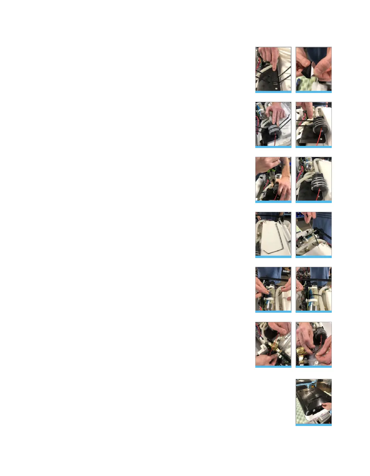
Pump Occlusion cont. :
Step 4: Reassemble the unit
• Fold the back panel into place, aligning the screw holes on either side.
• Re-insert the 2x 3/32” button head screws into the back panel.
• Re-install the base pan by aligning it with the screw in embossments
and the back panel.
• Using the 3/32”allen wrench or #2 Phillips screw driver, tighten all 13
screws on base pan. Figure 56
• Carefully turn unit back over (being mindful of the glass).
Figure 56
• Center the provided pressure-sensitive foam pad between the wire
ties on the pump mounting bracket. Figure 44 & 45
• Place new pump on top of the foam pad and tighten with the wire ties,
aligning them on top of the foam strips of pump (important: be certain
that the wire tie buckles are acclimated to the side of the pump – not
top). Figure 46 & 47
• With pump in one hand, use a set of pliers to pull and tighten the wire
ties until the pump is secure. Figure 48
• Clip the ties to the back of the buckle. Figure 49
• With the provided bent wire tie, feed the tie under the UV stainless
steel vessel, ensuring that the tie stays inside both ground wires.
Figure 50 & 51
• Tighten the wire tie and clip at the buckle. Figure 52 & 53
• Re-attach the pump harness to terminal 1. Figure 54
• With the provided 4” wire tie, secure the loose pump harness around
the ¼” silicon hose. Figure 55
• Tighten the wire tie and clip at the buckle.
Figure 44
Figure 47
Figure 50
Figure 53
Figure 45
Figure 48
Figure 51
Figure 54
Figure 46
Figure 49
Figure 52
Figure 55
 Loading...