Theme 22 Issue 2.1 09/07/01 Page 6 of 12
Fig. 6 Optional canopy trim
Final assembly
Following satisfactory installation of the convection
box into the opening, proceed as follows:
1. Secure the burner to the convection box
using the two screws provided, through the
holes in the front of the legs.
2. Connect the gas supply pipe to the inlet
elbow.
3. The ceramic components are fragile and
should be handled with care. Refer to Figs. 7
and 8 for positioning of ceramic fibre blocks
and coals.
4. Place the chair shaped back ceramic on the
burner, pushing it back against the upturned
edge of the burner plate.
5. Place the centre ceramics on the back
ceramic, pushing them back to sit comfortably
between the tapered sides.
6. Spring forward the slotted front plate and
slide the three front ceramics down as far as
the stops.
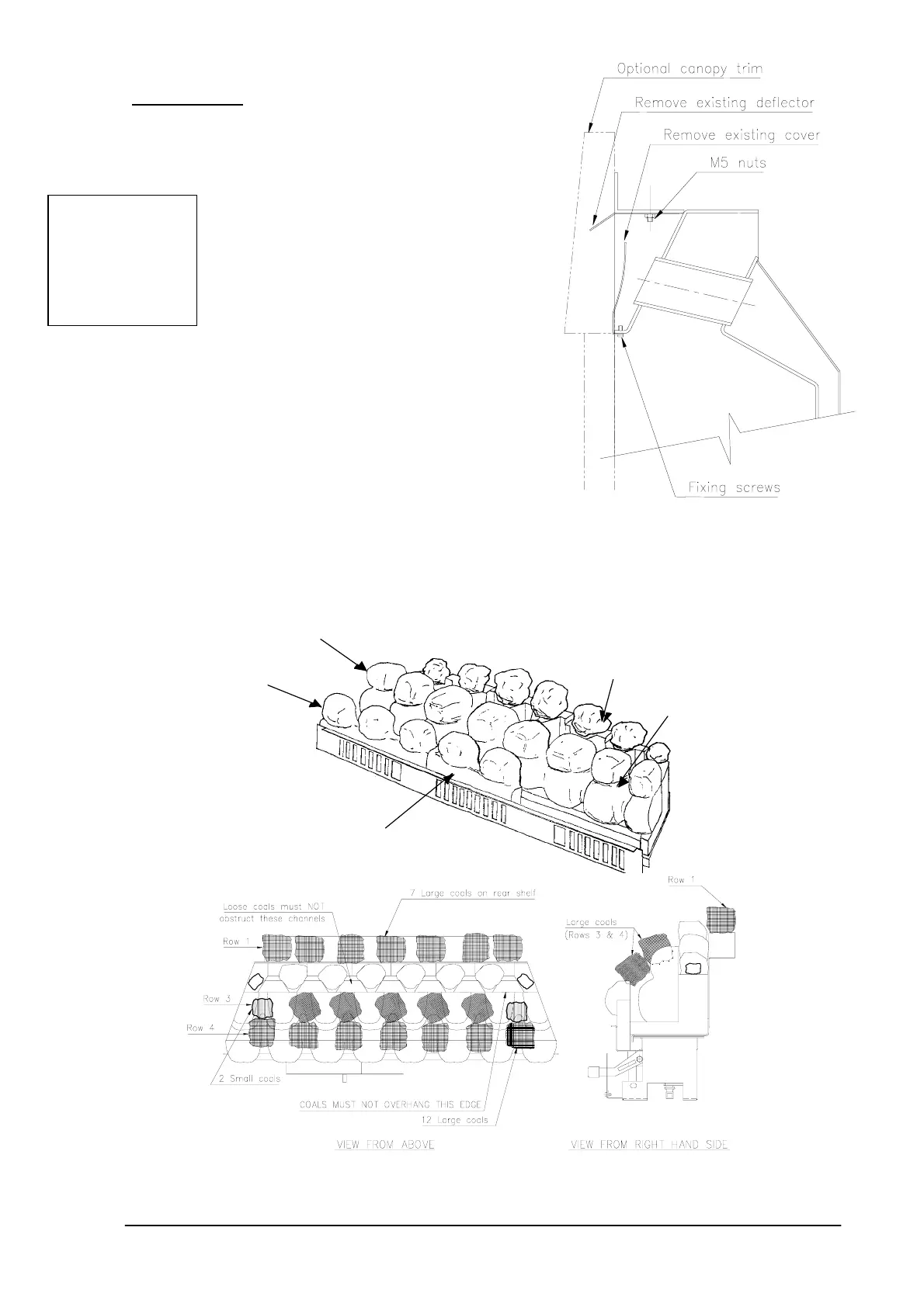
7. If a flat trim has been supplied it is attached to
the fire by means of four magnets. First
attach the magnets to the special raised pads
around the flange of the fire, and then attach the
trim to the magnets. If the optional canopy trim
has been supplied, first remove the existing front cover by undoing the two screws in its
bottom edge, and remove the small deflector by undoing the two M5 nuts. Neither item
is required. Secure the canopy trim using the screws which held the cover. (See Fig. 6)
WARNING: Always
blow pipework
through before
connecting to
appliance -
contamination will
permanently damage
the burner.
Fig.8 Placing the loose coals
Centre ceramic
(L.H.)
Front ceramic (L.H.)
Note: R.H. front ceramic
not shown for clarity
Front ceramic infill
Back ceramic
Centre cerami
(R.H.)
Fig. 7 Assembling the ceramic blocks