1 MA_141_142_A10-6-7-3-6-5_130617_en
Mechanic’s instructions
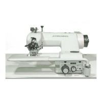
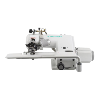
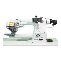
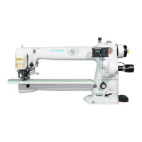
STROBEL Classes 141-23EV, -30, -40, -50, 142-30, -40
Contents
1 General notes on safety ............................................................................................ 5
2 General ..................................................................................................................... 7
2.1 Operating instructions ..................................................................................... 7
2.2 Class identification, serial number and orientation of the machine................. 7
2.3 Range of application and intended use .......................................................... 7
2.4 Technical Data ................................................................................................ 9
2.5 Brief setting instructions ............................................................................... 10
3 Disassemble the machine ....................................................................................... 11
3.1 Disassemble the main shaft (Fig. 1 and Fig. 2) ............................................ 11
4 Assemble the Machine ............................................................................................ 13
4.1 Mount the shaft (Fig. 1) ................................................................................ 13
4.2 Mount stitch regulating eccentric 353.0031 .................................................. 13
4.3 Adjust stitch regulating bolt 137.0014 for stitch adjustment .......................... 15
4.4 Adjust needle- and feed motion .................................................................... 15
4.5 Looper motion............................................................................................... 16
4.5.1 Adjust the looper motion .................................................................. 16
4.5.2 Adjust the looper eccentric (on single thread machines).................. 17
4.5.3 Adjust the looper eccentric (on two tread machines) ....................... 17
4.5.4 Adjust the front crank ....................................................................... 18
4.5.5 Set the looper in its front position to the feed cup ............................ 19
4.5.6 Adjust stroke of loop ........................................................................ 19
4.5.7 Adjust the front bearing block........................................................... 19
4.5.7.1 Basic dimensions for front and rear bearing block ........... 19
4.5.8 Adjust the rear bearing block ........................................................... 20
4.6 Adjust height of rear feed cups ..................................................................... 20
4.7 Mount the front feed cup .............................................................................. 20
4.8 Length adjustment of bar 133.0851 between stitch regulation rod and free
wheeling ....................................................................................................... 20
4.9 Thread lifting mechanism at needle bar head .............................................. 20
4.10 Spring tension at feed cup support arm 333.0114 ........................................ 21
4.10.1 Plate arm lifting ................................................................................ 21
4.11 Needle setting ............................................................................................... 22
4.11.1 Adjusting needle height (Fig. 10 and Fig. 11)................................... 22
4.12 Chaniging the looper .................................................................................... 23
4.13 Maintenance ................................................................................................. 24
4.14 General Data ................................................................................................ 24
218.05.10