5.2.3 Drive
The following mounting conditions must be observed:
• If possible, the drive should be engaged via a flexible connection, a flexible diaphragm coupling for example.
• The ideal drive is carried out over a torsionally-stiff flexible coupling with low axial and radial restoring forces.
This compensates for any misalignments and offsets, e.g. drive flange type F / F+M, see section 5.3.1.
• Observe the permissible shear force values, see section 4.1.7.
5.3 Optional equipment available
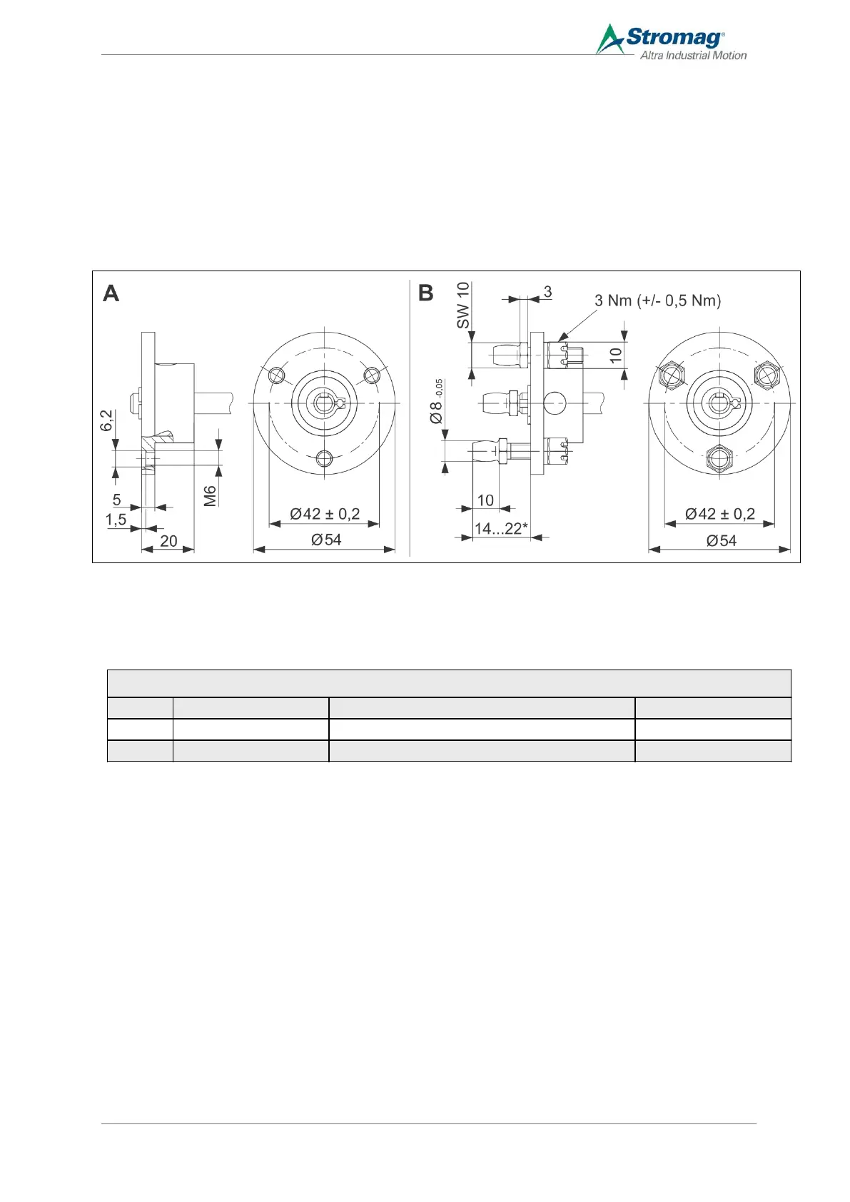
5.3.1 Drive Flange
A Elastic flange type F B Elastic flange type F+M
* Adjustment range
Implement the counter flange according to the dimensional drawing.
 Loading...