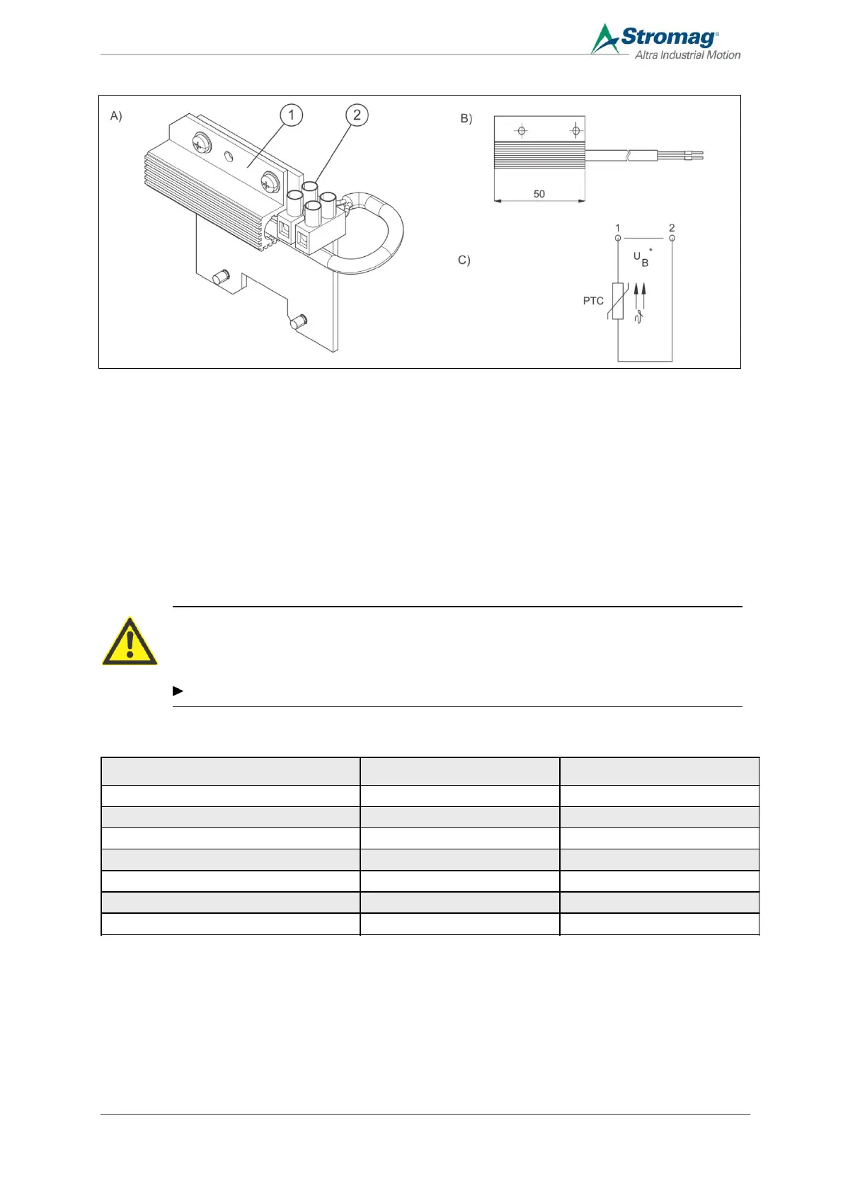
5.3.5 Ausführung mit Heizwiderstand
A PTC heating B View of PTC heating
1 PTC heating group C Circuit diagram
2 Connecting terminal
To avoid water condensation, a heating resistor can be mounted in the switch room. This heating is designed so
that a heat output of approx. 2.5 Watts or 4 Watts is available, depending on the voltage.
The electrical connection is (U
B
) 12 − 36 V AC/DC (max. 1,5 A AC/DC) or 110 − 250 V AC/DC (max. 4 A AC/ DC).
The PTC heating is self-regulating and temperature-limiting, and thus leads to an automatic adjustment to the
ambient temperature. The connection is via a 2-pole terminal block.
ATTENTION
Risk of accidents due to hot surfaces
The surface of the heating can exceed 60 °C.
Always allow components to cool down first.
Specific technical values
 Loading...