Design with incremental encoder X impulses per revolution of the drive shaft.
The drive shaft is guided through the GTES to the drive by the incremental
encoder.
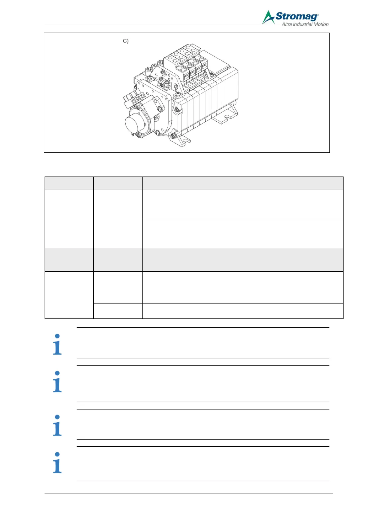
Design with multi-turn rotary encoder Output signals can be continued via a
terminal group or plug.
The drive shaft is guided through the GTES to the drive by the multi-turn rotary
encoder.
Design with single turn rotary encoder. Output signals can be continued via a
terminal group or plug.
The single turn rotary encoder is actuated via potentiometer coupling N.
Design with potentiometer. Output signals can be continued via a terminal
group.
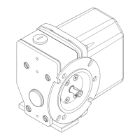
The drive is engaged via a clamp coupling for a shaft diameter of 6mm.
The position feedback system is possible in the following designs:
NOTE
For designs with potentiometers, the GCLS is supplied premounted. The potentiometer must be
securely mounted during assembly.
NOTE
For designs with Wertex absolute encoders, the response behaviour of the angle sensor can be
adjusted. The adjustment guidelines are enclosed as an extra appendix to this product and can also
be requested from the customer service department, see section 11.2.
NOTE
In the case of designs with a cUL listing, the mounted encoder must be operated with a “class 2”
power supply according to UL in order to maintain the listing.
NOTE
For the “N” variant, an additional adjustment level is optionally available. This can be used to adjust
the single-turn encoder or the potentiometer without simultaneously changing the switching point of
the last contact.
 Loading...