Do you have a question about the Stromberg Carlson Products CC-255 and is the answer not in the manual?
Confirm fit and clearance, check frame for interference, and consider propane tank access.
Attach lower pockets and back plates to the trailer frame, ensuring proper alignment and loose fit.
Secure tray plates to tray, upper pockets to plates, and insert vertical tubes into frame pockets.
Slide upper pockets onto tubes, position tray, drill holes, and secure with hardware and set screws.
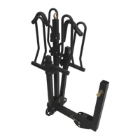
Connect lower mount to support mount, then attach upper and lower mounts to the tray assembly.
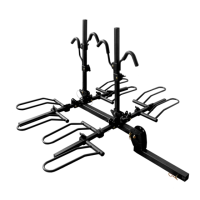
Identifies the main trailer tray (Figure A) and associated parts like support mounts and pockets.
Lists and illustrates various bolts, nuts, washers, and set screws (Figures J through O) required for assembly.
The Stromberg Carlson Trailer Tongue Mounted Trailer Tray, model # CC-255, is a cargo-carrying system designed to be mounted on the tongue of a trailer. Its primary function is to provide additional storage space for various items, such as propane tanks, coolers, generators, or other gear, thereby freeing up space inside the trailer or tow vehicle. The system is engineered for durability and secure transport of cargo.
The Trailer Tray system consists of a main tray (Figure A) supported by a robust framework that attaches to the trailer's A-frame or tongue. This framework includes vertical tubes (Figure B), upper support mounts (Figure C), lower support mounts (Figure D), upper pockets (Figure E), lower pockets (Figure F), lower mount back plates (Figure G), and additional lower mounts (Figure H). The tray itself features numerous holes and tie-down eyelets along its edges, allowing users to secure cargo using straps, bungee cords, or other tie-down methods. The design aims to keep cargo stable and accessible during travel.
The installation process involves mounting the lower pockets (Figure F) and lower mount back plates (Figure G) to the trailer frame using enclosed bolts and nuts (Figure K). These components should be positioned approximately 2-3 inches from the trailer body, with pockets on the outside of the frame and washers on the inside. The hardware should be connected loosely initially to allow for minor adjustments. The trailer tray plates (Figure I) are then attached to the sides of the main trailer tray (Figure A) using enclosed hardware (Figure M). Subsequently, the upper pockets (Figure E) are attached to these trailer tray plates using enclosed hardware (Figure L).
The vertical tubes (Figure B) are installed into the frame pockets, and the upper pockets are slid onto these tubes. A second person is recommended to stabilize the tray during this step due to its sturdy construction and weight. The tray's position should be adjusted, ideally 1-2 inches away from the trailer's front wall, to ensure proper clearance. Once the desired position is achieved, the vertical tubes are secured at the bottom and the tray assembly at the top using provided bolts and set screws (Figures N and O). This step requires drilling 3/8-inch holes through the vertical tubes. For accuracy and safety, it is recommended to mark the hole locations, dismantle the tray, drill the holes (drilling halfway from each side to ensure alignment), and then reassemble. Finally, all nuts should be tightened, ensuring the tray remains 1-2 inches from the front trailer wall.
The lower mount (Figure H) is connected to the lower support mount (Figure D) using two holes nearest the outside of the A-frame and enclosed hardware (Figure J), again loosely at first for adjustment. The upper support mount (Figure C) and lower support mount (Figure D) are connected using enclosed hardware (Figure L). The upper support mount is then attached to the trailer tray (Figure A) using enclosed hardware (Figure L), with the lower mount's location adjusted for proper attachment. All hardware is then tightened.
| Brand | Stromberg Carlson Products |
|---|---|
| Model | CC-255 |
| Category | Automobile Accessories |
| Language | English |