- 14 -
Cont ...
Step 2:
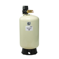
The vessel assembly should then be positioned and checked to ensure there is
sufficient space to install the upstream line-in kit between the stopcock and
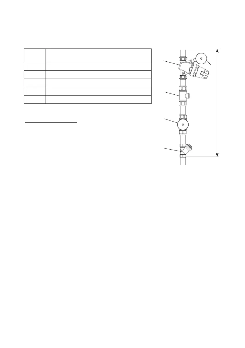
pressure vessel inlet. Refer to the chart below as a guide.
Pipe
Size
Minimum pipe length required to install the
upstream line-in kit (mm) (A)
22 mm 480 mm
28 mm 580 mm
35 mm 630 mm
40 mm 735 mm
54 mm 820 mm
Upstream line-in kit
The upstream line-in kit includes:
1 - inline strainer
2 - pressure gauge (upstream)
3 - double check valve
4 - pressure reducing valve
5 - pressure gauge (fitted to pressure reducing
valve)
6 - Mainsboost vessel connector (see step 1)
The above components must be installed in the correct order to ensure safe and
satisfactory system operation.
Fig. 19
A
5
4
3
2
1