- 18 -
Cont ...
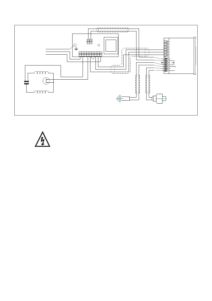
7.18 Wiring diagram:
7.19 Fuse: All models should be protected by a 3 Amp fuse.
7.20 Supply cord replacement:
The internal wiring within the terminal box is routed and
secured to ensure compliance with the electrical standard
EN 60335-1. It is essential that prior to any disturbance of
this internal wiring, all cable routing and securing details are
carefully noted to ensure re-assembly to the same factory
pattern is always maintained.
7.21 If the supply cord is to be changed or damaged, it must be replaced by a special
cord available from Stuart Turner or one of its approved repairers.
MAIN WINDING
THERMOTRIP
CAPACITOR
START WINDING
B
L
U
E
B
LA
C
K
L
E
N
230 VAC/1PH/50Hz
SUPPLY
GREEN/YELLOW
BROWN
BLUE
1
2
3
4
5
6
CONTROLLER
BLUE (LINK WIRE)
BROWN
BROWN
TEMPERATURE
SENSOR
PRESSURE
BLUE
BROWN
BROWN
BLUE
BLACK
BLUE
BLACK
BROWN
BROWN
BLUE
BROWN
BLUE
BLUE
BROWN
BLUE
BROWN
N N1 N2
L5
L4 L3 L2 L1 L
12 VAC
7
8
9
10
12 -VE
13 +VE
BLUE
BLUE (LINK WIRE)
NOT USED NOT USED
11
Fig. 25