)¥[U]©[E[M]
PR99
MKIII
3/5
®
1
p^oaDcaD
^
@
)
°/
3.8.
Rechten Wickel
motor
ausbauen
—
Bremstrommein
ausbauen (siehe3.5.).
—
2
Schrauben fur
Querstrebenbefestigung
Ibsen.
Querstrebe entfernen.
—
4
Steckverbindungen
von
Motoran-
schlusskabel
auf Fader
Start
Logic
ausziehen
(brn, blu,
yei, grn).
Kabel freilegen
(Bride
entfer-
nen).
—
Rechten
Wickelmotor
von
Hand
f^t-
halten
und
3
Motor-Befestigungsschrauben
Ibsen.
--
Rechten
Wickelmotor
vorsichtig
aus-
fahren.
3.9.
Linken Wickelmotor
ausbauen
—
Bremstrommein
ausbauen
(siehe3.5.).
2 Schrauben
fur
Querstrebenbefestigung
Ibsen.
Querstrebe
entfernen.
—
4
Steckverbindungen
von
Motoran-
schlusskabel
auf
Stromversorgungsplatine
aus-
ziehen
(yel,
blu,
brn,
grn).
Kabel
freilegen.
—
Netzanschluss-Einheit mit 2 Schrauben
yon Netztrafo
Ibsen und
hinausdrehen.
—
Linken
Wickelmotor
von Hand fest-
halten
und
3
Motor-Befestigungsschrauben
Ibsen.
—
Linken Wickelmotor vorsichtig
aus-
fahren.
Beim Einbau
ist
darauf
zu
achten,
dass
der
Wickelmotor zentriert
wird.
Der
Spulen-
teller
darf an eingebauter
Laufwerkabdeckung
nicht
streifen.
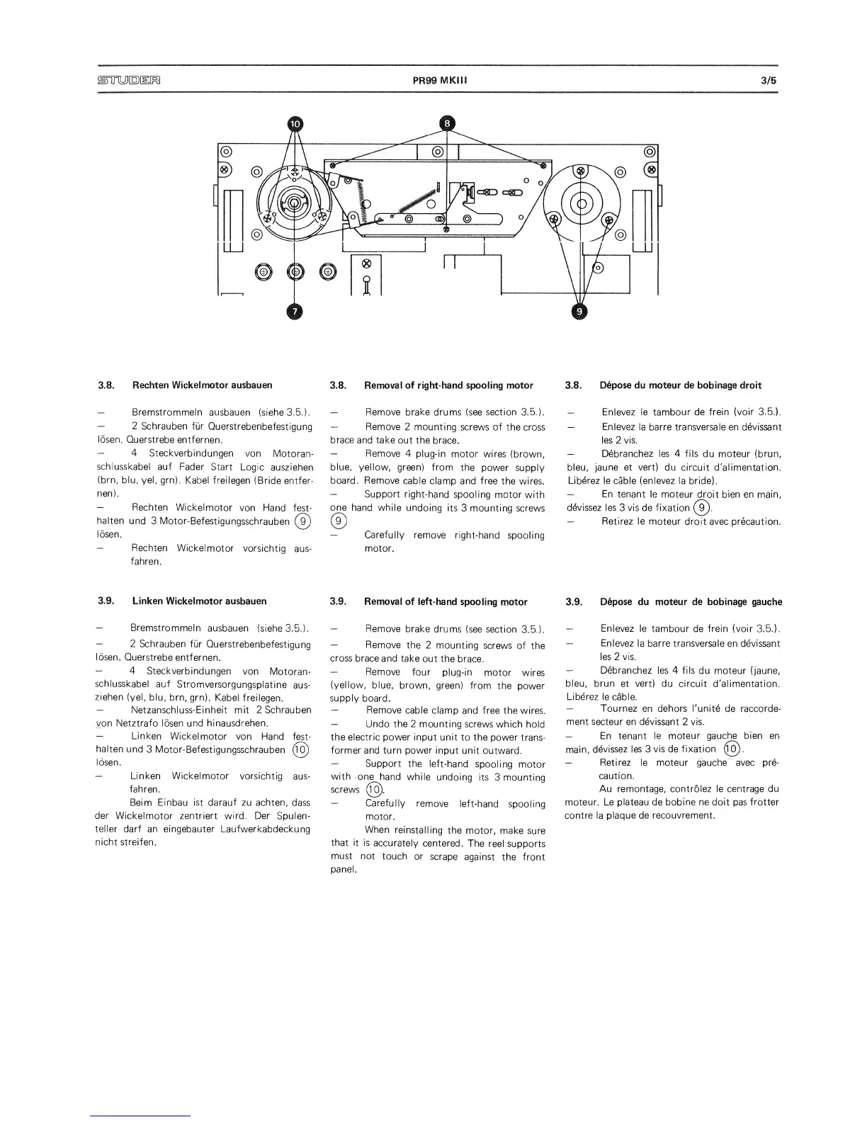
3.8. Removal
of right-hand spooling motor
—
Remove
brake drums (see
section
3.5.).
—
Remove
2
mounting
screws of
the
cross
brace and
take
out the
brace.
—
Remove
4
plug-in
motor
wires
(brown,
blue, yellow,
green)
from
the
power supply
board. Remove
cable
clamp and
free the wires.
—
Support right-hand
spooling motor
with
Oj]e hand while
undoing
its
3
mounting
screws
(£)
—
Carefully
remove
right-hand
spooling
motor.
3.9.
Removal
of left-hand
spooling
motor
—
Remove
brake
drums
(see section
3.5.).
—
Remove
the
2 mounting
screws
of
the
cross
brace and
take
out
the brace.
—
Remove
four
plug-in
motor
wires
(yellow,
blue,
brown,
green)
from
the
power
supply
board.
—
Remove
cable
clamp and free
the wires.
—
Undo the 2 mounting
screws
which
hold
the electric
power input unit
to the
power trans-
former and turn power input
unit
outward.
—
Support the
left-hand
spooling
motor
with
one
hand
while
undoing
its
3 mounting
screws
(^.
—
Carefully
remove
left-hand
spooling
motor.
When
reinstalling
the
motor,
make
sure
that
it
is
accurately
centered.
The
reel
supports
must not
touch
or scrape
against the
front
panel.
3.8.
Depose du moteur de bobinage droit
—
Enlevez le tambour
de
frein (voir 3.5.).
—
Enlevez
la bar
re
transversale en devissant
les 2 vis.
—
Debranchez les
4
fils
du moteur (brun,
bleu, jaune et
vert)
du circuit d'alimentation.
Liberez le cable (enlevez
la bride).
—
En
tenant le
moteur droit bien en main,
devissez
les
3
vis
de
fixation
(^.
—
Retirez
le
moteur droit avec precaution.
3.9. Depose du moteur de bobinage gauche
—
Enlevez
le tambour
de
frein (voir
3.5.).
—
Enlevez
la bar re transversale
en
devissant
les 2 vis.
—
Debranchez les 4
fils du
moteur (jaune,
bleu,
brun
et
vert)
du circuit d'alimentation.
Liberez
le cable.
—
Tournez en dehors I'unite
de raccorde-
ment secteur
en devissant
2
vis.
—
En tenant
le moteur gauche bien en
main,
devissez
les 3
vis
de
fixation .
—
Retirez le moteur gauche avec pre-
caution.
Au remontage,
controlez le centrage du
moteur. Le
plateau
de
bobine ne doit pas frotter
contre
la
plaque de recouvrement.
 Loading...