DTry[D)[i[R]
PR99
MKfl
3/6
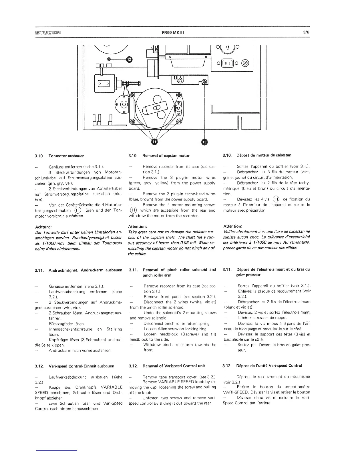
3.10.
Ton
motor
ausbauen
3.10.
Removal
of capstan
motor
3.10.
Depose
du moteur
de
cabestan
—
Gehause
entfernen
(siehe
3.1
.).
—
3
Steckverbindungen
von
Motoran-
schlusskabe!
auf
Stromversorgungsplatine
aus-
ziehen
(grn,
gry,
yel).
—
2
Steckverbindungen
von
Abtasterkabel
auf
Stromversorgungsplatine
ausziehen
(blu,
brn).
—
Von
der
Geratmickseite
die 4
Motorbe-
festigungsschrauben
(h)
losen
und
den
Ton-
motor
vorsichtig
ausfahren.
Achtung:
Die
TonWelle
darf
unter
keinen
Umstanden
an-
geschlagen
warden.
Rundlaufgenauigkeit
besser
als
1/1000 mm.
Beim
Einbau
des
Ton
motors
keine
Kabel
einklemmen.
—
Remove
recorder from its case (see sec-
tion 3.1
.).
—
Remove
the
3
plug-in motor wires
(green, grey,
yellow) from
the power
supply
board.
—
Remove
the
2
plug-in tacho-head wires
(blue, brown) from the power
supply board.
—
^
Remove the 4 motor
mounting screws
which are
accessible from
the rear and
withdraw
the motor from the recorder.
Attention:
Take great
care not to
damage
the
delicate
sur-
face
of
the
capstan
shaft.
The
shaft has a
run-
out
accuracy
of better
than 0.05
mil. When re-
installing
the
capstan motor
do
not
pinch any
of
the
cables.
—
Sortez
I'appareil du boTtier
(voir 3.1.).
—
Debranchez
les
3
fils du moteur
(vert,
gris et
jaune) du
circuit
d'alimentation.
—
Debranchez
les 2
fils
de la
tete
tachy-
metrique
(bleu et
brun) du
circuit d'alimenta-
tion.
—
Devissez
les
4 vis
(2)
de fixation
du
moteur
a
I'interieur
de
I'appareil et
sortez le
moteur
avec precaution.
Attention:
VeiHez
absolument a
ce
que Taxe
de
cabestan ne
subisse
aucun
choc.
La
tolerance
d'excentricitS
est
inferieure
a 1/1000
de mm.
Au
remontage,
prenez
garde de
ne
pas coincer
des
cables.
3.1
1.
Andruckmagnet,
Andruckarm
ausbauen
3.1 1.
Removal
of
pinch
roller
solenoid
and
3.1
1 .
Depose de
I'electro-aimant
et du
bras du
pinch
roller
arm
galet
presseur
—
Gehause
entfernen
(siehe
3.1
.).
—
Laufwerkabdeckung entfernen
(siehe
3.2.).
—
2 Steckverbindungen
auf Andruckma-
gnet ausziehen
(wht, vio).
—
2 Schrauben
losen.
Andruckmagnet aus-
fahren.
—
Ruckzugfeder losen.
—
Innensechskantschraube
an Stellring
losen.
—
Kopftrager losen
(3
Schrauben)
und
auf
die
Seite kippen.
—
Andruckarm nach
vorne
ausfahren.
—
Remove recorder from
its case
(see
sec-
tion 3.1
.).
—
Remove front panel (see
section 3.2.).
—
Disconnect the 2 wires
(white, violet)
from the pinch
roller
solenoid.
—
Undo the solenoid's 2
mounting screws
and
remove solenoid.
—
Disconnect
pinch roller return spring.
—
Loosen
Alien-screw on locking
ring.
—
Loosen
headblock
(3
screws) and
tilt
headblock
to
the side.
—
Withdraw
pinch roller
arm towards the
front.
—
Sortez I'appareil du
boitier
(voir 3.1.).
—
Enlevez
la
plaque de
recouvrement
(voir
3.2.).
—
Debranchez les 2
fils de
I'electro-aimant
(blanc et
violet).
—
Devissez 2
vis
et
sortez
I'electro-aimant.
—
Liberez le ressort de
rappel.
—
Devissez
la vis imbus
a
6
pans de I'an-
neau de
blocquage et basculez-le sur le
cote.
—
Devissez
le support
des tetes
(3
vis)
et
basculez-le sur le
c6te.
—
Sortez
par I'avant le
bras du galet pres-
seur.
3.12. Vari-speed Control-Einheit
ausbauen 3.1 2. Removal
of Varispeed
Control
unit
3.12.
Depose de
I'unit6
Vari-speed
Control
—
Laufwerksabdeckung
ausbauen (siehe
3.2.).
—
Kappe des
Drehknopfs VARIABLE
SPEED
abnehmen,
Schraube
losen und
Dreh-
knopf
abziehen
—
zwei Schrauben
losen
und
Vari-Speed
Control
nach hinten
herausnehmen
—
Remove tape
transport cover (see
3.2.)
—
Remove
VARIABLE
SPEED
knob by
re-
moving the
cap,
loosening the
screw
and
pulling
off the knob
—
Unfasten two
screws and
remove
vari-
speed
control
by
sliding
it
out
toward
the
rear
—
Deposer
le
recouvrement
du
mecanisme
(voir
3.2.)
—
Retirer le bouton du potentiometre
VARI-SPEED.
Devisser la vis
et
retirer le bouton
—
Devisser
deux
vis
et extraire le Vari-
Speed
Control par I'arriere
 Loading...