PR99 1VlKili
4/3
4.3.2.
Einsteilung
des
Andruckaggregates
4.3.2. Adjustment of the pinch roller
mechanism
—
Gerat auf
PLAY
schalten.
Wenn kein
Band
eingelegt
ist, Lichtoffnung am
optischen
Endschalter
abdecken.
—
Andruckmagnet
soweit nach
rechts ver-
schieben,
dass
zwischen Mitnehmer
und An-
druckarm
ein
Abstand
B
von 1mm
entsteht
—
Andruckmagnet
arretieren.
—
Kontrollieren,
ob der
Anker
des
An-
druckmagneten am
Anschlag steht.
Andruckarm
leicht
von
der Capstan-
Welle
wegziehen, dabei darf sich der Anker
nicht bewegen.
—
Befestigungsschrauben des Andruckma-
gneten
mit einem Lacktropfen sichern.
—
Andruckkraft kontrollieren und wenn
notig mit Schraube
C
justieren.
(Fig.
4.3.—
2).
—
Press
button PLAY. If
no tape is laced
on the recorder,
block the light port of
the end
of the
tape switch
by
suitable
means.
—
Shift
pinch roller solenoid
to the right
until
a
clearance of
1mm
is reached at
point
B.
—
Lock pinch roller solenoid in this posi-
.
tion.
—
Check to
make sure that
the
plunger has
fully
bottomed. The plunger must
not
move
when pulling the pinch roller
arm
slightly
away
from
the capstan shaft.
—
Secure
the
solenoid's mounting screws
with
a
drop of
sealing lacquer.
—
Measure pinch roller force
and adjust
with screw
C
if
necessary,
(fig.
4.3.—
2)
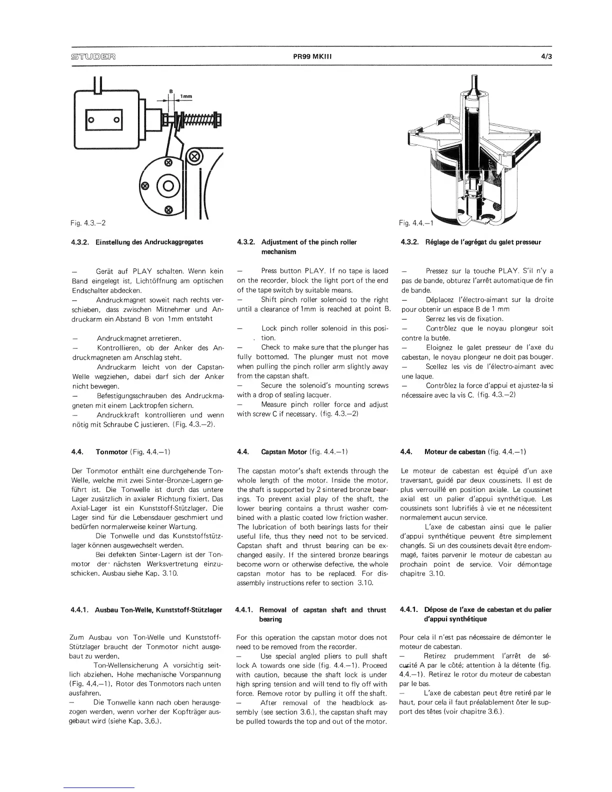
4.4. Tonmotor (Fig.
4.4.—
1)
Der
Tonmotor enthalt eine durchgehende Ton-
Welle,
welche
mit
zwei
Sinter-Bronze-Lagern
ge-
fuhrt ist. Die Tonwelle ist durch das untere
Lager zusatzlich in axialer Richtung fixiert.
Das
Axial- Lager ist ein Kunststoff-Stutzlager. Die
Lager sind
fur
die
Lebensdauer
geschmiert
und
bedurfen normalerweise keiner Wartung.
Die Tonwelle und das Kunststoffstutz-
lager konnen ausgewechselt werden.
Bei defekten Sinter- Lagern ist
der Ton-
motor
der’ nachsten
Werksvertretung einzu-
schicken.
Ausbau siehe Kap.
3.1
0.
4.4. Capstan
Motor
(fig.
4.4.—
1
)
The capstan motor's
shaft extends through the
whole
length
of
the motor. Inside the motor,
the shaft
is supported by 2
sintered bronze bear-
ings. To prevent axial play of the
shaft, the
lower bearing
contains
a
thrust washer com-
bined with
a
plastic
coated low friction washer.
The lubrication of both bearings lasts
for
their
useful life, thus
they need not to be serviced.
Capstan
shaft
and thrust bearing
can
be ex-
changed easily. If the sintered
bronze bearings
become worn
or otherwise
defective, the whole
capstan
motor has to be replaced.
For dis-
assembly instructions refer
to
section
3.10.
4.4.1
.
Ausbau
Ton-Welle,
Kunststoff-Stutzlager
Zum
Ausbau
von Ton-Welle und
Kunststoff-
Stutzlager
braucht der
Tonmotor
nicht
ausge-
baut zu werden.
Ton-Wellensicherung A vorsichtig seit-
lich
abziehen.
Flohe
mechanische Vorspannung
(Fig.
4.4.—
1
).
Rotor des Tonmotors nach unten
ausfahren.
—
Die
Tonwelle
kann
nach oben
herausge-
zogen
werden,
wenn vorher
der
Kopftrager
aus-
gebaut
wird (siehe
Kap.
3.6.).
4.4.1.
Removal of
capstan shaft
and
thrust
bearing
For
this
operation the capstan motor does not
need
to
be removed from the recorder.
—
Use
special angled pliers to pull
shaft
lock
A towards one side
(fig.
4.4.—
1).
Proceed
with caution, because the
shaft
lock is under
high spring tension and
will
tend to fly
off
with
force. Remove rotor by
pulling it off
the shaft.
—
After removal of the headblock as-
sembly
(see
section
3.6.),
the capstan shaft
may
be pulled towards the top and out of the motor.
4.3.2.
Regiage de I'agr^gat du galet presseur
—
Pressez sur la
touche
PLAY. S'il n'y a
pas de
bande,
obturez I'arret
automatique
de
fin
de bande.
—
Deplacez
I'electro-aimant
sur
la
droite
pour
obtenir un
espace B de
1
mm
—
Serrez les vis de
fixation.
—
Controlez que le
noyau
plongeur soit
contre la
butee.
—
Eloignez le galet
presseur
de I'axe du
cabestan,
le noyau
plongeur
ne doit pas
bouger.
—
Scellez
les vis de
I'electro-aimant
avec
une laque.
—
Controlez la
force d'appui
et ajustez-la
si
n^cessaire avec la
vis
C.
(fig.
4.3.—
2)
4.4. Moteur de cabestan (fig.
4.4.—
1
)
Le
moteur de cabestan
est equipe d'un axe
traversant, guide
par
deux
coussinets. II est de
plus verrouille en
position axiale. Le coussinet
axial est un palier
d'appui synthetique.
Les
coussinets sont lubrifies
a
vie et ne
necessitent
normalement
aucun service.
L'axe de
cabestan ainsi que le
palier
d'appui synthetique
peuvent
etre
simplement
changes. Si un des
coussinets devait
etre
endom-
mage, faites parvenir
le moteur
de cabestan
au
prochain point de
service. Voir demontage
chapitre 3.10.
4.4.1.
Depose de I'axe de cabestan et
du palier
d'appui
synthetique
Pour cela il n'est
pas
n4cessaire
de demonter le
moteur de cabestan.
—
Retirez
prudemment I'arret de
se-
curite A par le cote;
attention
a
la detente
(fig.
4.4.—
1
).
Retirez le rotor du moteur
de cabestan
par le bas.
—
L'axe de cabestan peut etre retire par
le
haut,
pour
cela
il
faut prealablement oter
le
sup-
port des tetes (voir chapitre
3.6.).
 Loading...