)TPPH[Mi
PR99
MKIII
5/2
5.3.
Line
Input 1.177.515/521
Der Eingangsverstarker enthait zwei
symmetri-
sche
Eingange
mit Trafo. Ihnen foigt eine in
der
Verstarkung
regelbare Stufe zur Anpassung
an
verschiedene
Leitungspegel. Mit
dem
CMOS
Schalter
iC3
kann zwischen
kaiibriertem
und
unkalibriertem
Eingangspegel umgeschaltet
war-
den. Im unkalibrierten
Betrieb kann mit
den
Eingangsreglern
die Empfindlichkeit
urn max.
lOdB erhoht werden.
Nach dem
CAL/UNCAL
Schalter erfoigt
das
fur
einkanalige Aufnahmen
mogliche Zusammenmischen
der Eingangssigna-
le. Die
Querverbindung erfoigt
uber FET's,
wel-
che
liber die
Aufnahmevorwahitasten aktiviert
werden.
5,4.
Aufnahme-Verstarker
1.177.230/232/233
Dieser Print
enthait
eine
Stummschaltung,
Auf-
nahme-Entzerrung
und die
Treiberstufe fiir
beide
Kanale.
Die
Stummschaltung schliesst den
Signalpfad
so
lange kurz, bis die Relaiskontakte
sicher
geschlossen sind.
Erst
danach wird der
Signalpfadfreigegeben,
dies
erfoigt "Knacks-frei".
Das
Signal
wird vom Sammelschienenpegel von
ca,
80
mV
(fur
Vollausteuerung)
in
den Stufen
Q1
und
Q2
(Q5
und
Q6)
verstarkt und gemass
der
Einstellung
an
R12, resp.
R7 (R27 resp.
R22)
entzerrt. Die Tiefen-Entzerrung
ist mit
C7
(C20) und
den
Seriewiderstanden
R12
+
R7
(R27
+
R22)
auf
3180
jus
festgelegt
(nur
NAB-
Version).
Mit R13 (R28)
wird der Aufnahme-
zweig
so gepegelt,
dass
bei
Vor/Hinterband-Um-
schaltung
kein Pegelsprung
auftritt.
Im
Ermitterzweig
der
Treiberstufe
Q3,
Q4
(Q7,
Q8)
liegt als
Stromgegenkopplung
ein
38
kHz
MPX-Filter
zur
Vermeidung
von
Inter-
ferenzen
mit
der
Vormagnetisierungsfrequenz.
Das
HF-Sperrfilter LI,
C16
(L3,
C27)
ist auf die
Oszillatorfrequenz
abgleichbar und
schutzt die
Treiberstufe.
5.3.
Line Input
1.177.515/521
The
input amplifier
has
two transformer
bal-
anced inputs
followed
by
an
adjustable amplifier
stage
to
adapt the different line
levels. With
the
CMOS
ICS switch, it is
possible
to commute
be-
tween the
calibrated
and uncalibrated
levels, in
UNCAL
mode
it is
possible to increase
the sensi-
tivity
by
10
dB with
the input
potentiometers.
Following
the CAL/UNCAL
network the mixing
of
both inputs
takes place
only
when recording
on one
channel is
selected.
The mixing
occurs
via
FET's
activated
by the safe/ready
selectors.
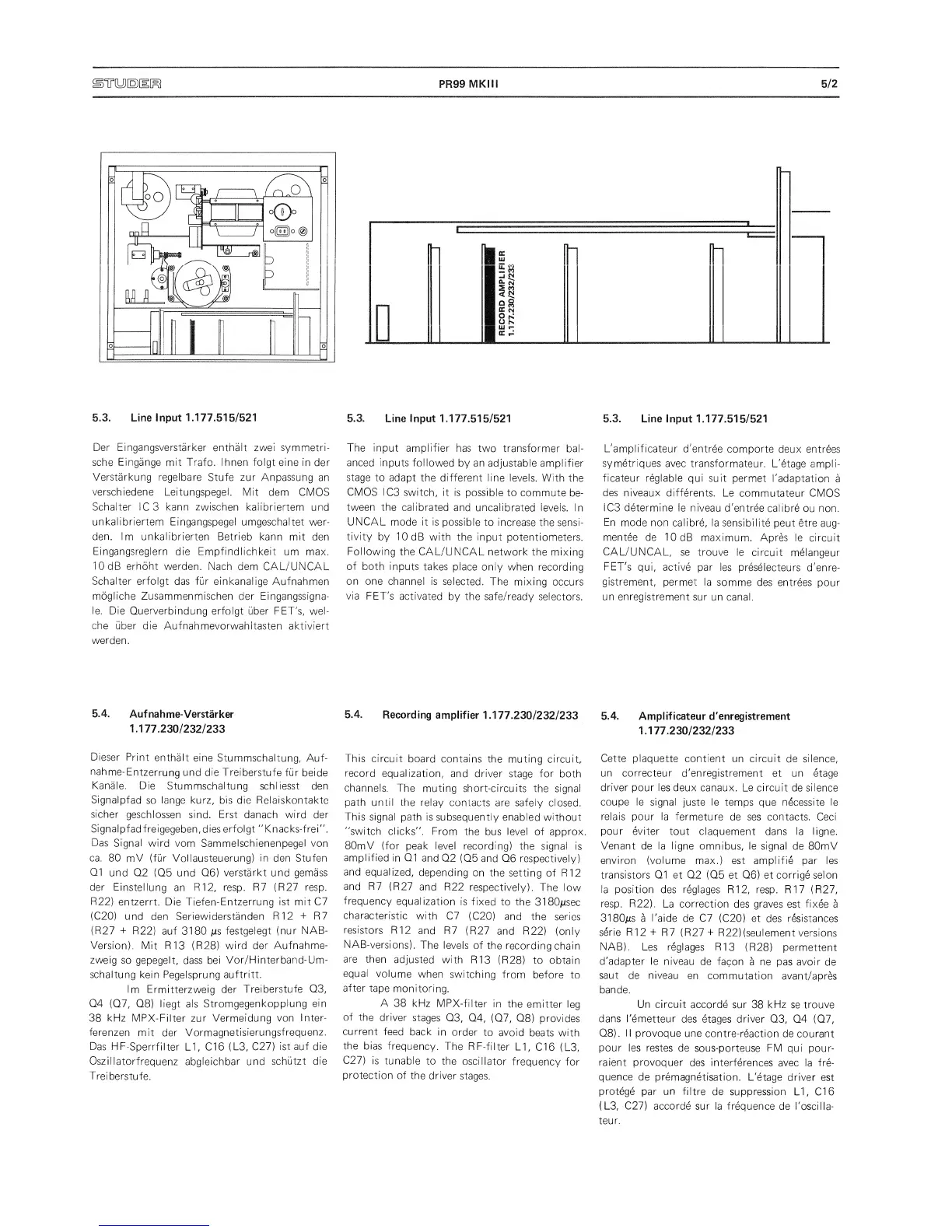
5.4.
Recording
amplifier
1.177.230/232/233
This
circuit
board contains
the muting circuit,
record
equalization,
and
driver
stage for
both
channels. The
muting short-circuits
the signal
path
until
the relay
contacts are safely closed.
This
signal path is
subsequently enabled
without
"switch
clicks".
From the
bus
level
of approx,
80mV (for
peak level
recording) the signal
is
amplified
in Q1
and
Q2 (Q5
and Q6
respectively)
and
equalized,
depending
on
the setting
of R12
and R7
(R27
and R22
respectively).
The
low
frequency
equalization
is fixed
to
the
3180jusec
characteristic
with
C7
(C20)
and
the series
resistors
R12
and R7
(R27
and R22)
(only
NAB-versions).
The levels
of the recording
chain
are then
adjusted
with
R13
(R28)
to
obtain
equal
volume
when
switching
from
before
to
after
tape
monitoring.
A
38
kHz
MPX-filter
in
the
emitter
leg
of
the
driver
stages
Q3,
Q4,
(Q7,
Q8)
provides
current
feed back
in
order
to
avoid
beats with
the
bias
frequency.
The
RF-filter
LI,
C16
(L3,
C27)
is
tunable
to the
oscillator
frequency
for
protection
of
the driver
stages.
5.3. Line
Input
1.177.515/521
L'amplificateur d'entree
comporte deux
entrees
symetriques avec
transformateur.
L'etage
ampli-
ficateur reglable
qui suit
permet
I'adaptation
a
des
niveaux differents.
Le
commutateur CMOS
IC3
determine
le niveau
d'entree calibrb
ou non.
En
mode non calibre,
la sensibilite
peut etre
aug-
mentee
de lOdB
maximum. Apres
le circuit
CAL/UNCAL,
se trouve
le circuit
melangeur
FET's
qui, active
par
ies preselecteurs
d'enre-
gistrement,
permet la
somme
des entrees
pour
un
enregistrement
sur un
canal.
5.4.
Amplificateur
d 'enregistrement
1.177.230/232/233
Cette
plaquet.te contient un circuit
de silence,
un correcteur
d'enregistrement
et
un etage
driver pour Ies
deux canaux. Le circuit
de
silence
coupe le signal
juste le temps
que
necessite le
relais
pour la fermeture
de ses contacts. Ceci
pour eviter
tout claquement
dans
la ligne.
Venant
de
la ligne
omnibus, le signal
de
80mV
environ (volume
max.) est amplifie par Ies
transistors 01 et
02 (05
et
06)
et corrige
selon
la position
des
reglages
R12, resp. R17 (R27,
resp. R22).
La correction
des
graves est fixee
a
3180jus
a
I
'aide
de C7
(C20)
et
des
resistances
serie
R12
+
R7 (R27
+
R22)
(seulement
versions
NAB),
Les reglages
R13
(R28)
permettent
d'adapter le
niveau
de facon
a
ne
pas avoir
de
saut
de
niveau
en
commutation
avant/apres
bande.
Un circuit
accorde
sur 38
kHz
se trouve
dans
I'emetteur
des etages driver
03,
04
(07,
08).
II
provoque une
contre-reaction de courant
pour les restes
de
sous-porteuse
FM
qui
pour-
raient provoquer
des interferences
avec
la fre-
quence
de premagnetisation.
L'etage driver
est
protege
par
un
filtre
de suppression LI,
Cl
6
(L3, C27) accorde sur la frequence
de I'oscilla-
teur.
 Loading...