27
M
INI-SPACE EC INSTALLATION, OPERATION AND MAINTENANCE MANUAL
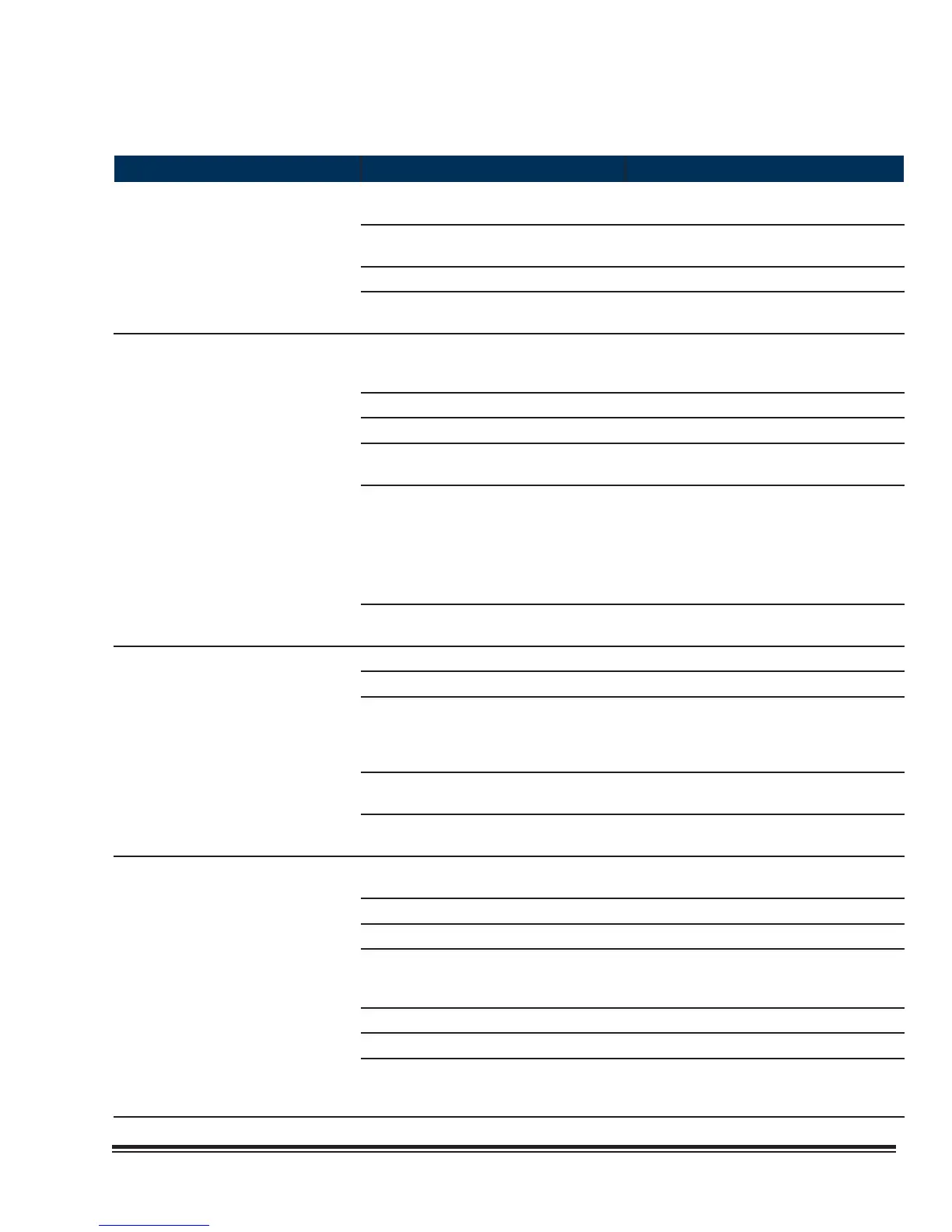
SYMPTOM PROBABLE CAUSE RECOMMENDATION
System Short of Capacity
a. Low refrigerant (indicated by bubbles in
sight glass).
Check for leaks Repair and recharge
system.
b. Expansion valve stuck or obstructed
(short cycling or continuous running).
Remove valve and clear obstruction or
replace valve.
c. Clogged drier/strainer (feels cold). Replace with new drier/ strainer.
d. Reduced airfl ow. Check belt tension, fi lters and clear evapo-
rator coil of debris.
Compressor Short Cycles
a. Low line voltage causing compressor to
overheat.
Check power source for cause of low line
voltage.
b. Dirty or iced over evaporator coil. Defrost and/or clean coil.
c. Reduced airfl ow (when applicable). Check fi lter and belt tension.
d. Lack of refrigerant. Check for leak. Repair and recharge sys-
tem.
e. Short cycling of conditioned air. 1. Supply and/or return grilles are incorrectly
oriented. Re-orient.
2. Supply and return grilles are too close
together. Move further apart.
3. Insuffi cient heat load. Add temporary heat
load to compensate.
f. Remote temperature sensor is improperly
located.
Check for supply registers that may be too
close to thermostat. Relocate if necessary.
Heater Inoperative a. Fuses blown. Check for short circuit, replace fuse.
b. Temperature set too low. Increase temperature set point.
c. Overheat switch open. Insuffi cient airfl ow across heater elements.
Check for dirty fi lters or obstructions that
may reduce airfl ow. Correct or replace as
needed.
d. Manual-reset overheat safety switch
tripped.
Reset manual overheat safety switch (See
item immediately above).
e. Heater element burned out. Check continuity with an ohmmeter. Re-
place heater element.
Humidifi er Inoperative
Note: See humidifi er
manual for additional help.
a. Water supply has been turned off or not
connected.
Connect and/or turn on water supply.
b. Humidifi er switch is in “Off” position. Turn switch to “Auto/On” position.
c. Electrical connections are loose. Tighten electrical connections.
d. Humidifi er circuit breaker tripped. Check for over current by the humidifi er
electrodes. Drain water from tank and refi ll.
Reset circuit breaker.
e. Relative humidity is above set point. Adjust humidistat set point.
f. Humidistat yellow status LED is fl ashing. Consult humidifi er manual.
g. Water conductivity is too low. Add a teaspoon of table salt to the water
through the top of the cylinder. Typically
only required on initial start-up.