ASSEMBLY INSTRUCTIONS
Hardware Used
6. Place the large end cap (CC) onto the short
tapered tube (E).
Place the tapered end of the short tapered tube (E)
into the untapered end of the bottom tube
assembly, as shown.
Large End Cap
x 1
CC
CC
7
7
Hardware Used
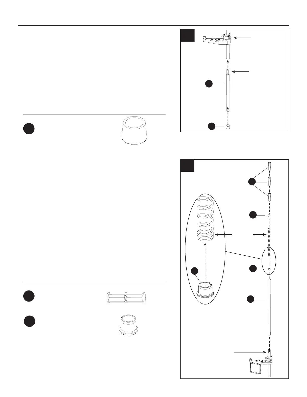
7. NOTE: ASSEMBLY SHOWN FOR 96 IN. OPENING
HEIGHT. The following assembly should be modied
based on your opening height, SEE CHART ON
PAGE 4.
Insert the spring stoppers (FF) into the ends of the
spring, as shown. NOTE: Spring is packed inside
straight tube (B).
Place straight tube (B) on top of the assembly and
insert three spacers (AA) into the straight tube (B),
as shown.
Spring Stopper
x 2
FF
6
E
tapered end
at the top
bottom tube
assembly
Spacer
x 3
AA
spring
B
tapered end
at the top
FF
FF
FF
AA
IS2265
 Loading...