8
8
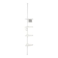
Hardware Used
8. Place the small end cap (BB) onto the 3/4 in. tube (A).
Insert the transition ring (EE) into the straight tube (B).
Slide the 3/4 in. tube (A) through the transition
ring (EE) and into the straight tube (B), as shown.
Place the tape strips (GG) around the seams of
the tubes.
NOTE: After inserting the 3/4 in. tube (A) into
the straight tube (B) ensure that the transition
ring (EE) ts snuggly over the straight tube (B).
Transition Ring x 1
EE
Small End Cap
x 1
BB
B
BB
EE
GG
Tape Strip
x 1
A
B
A
B
C
GG
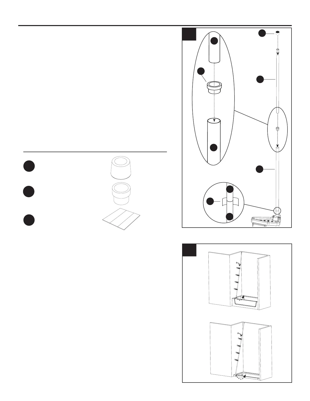
9. NOTE: Make sure you are installing in a clean,
dry and safe environment.
Compress the TOP of the unit against the ceiling in
the desired location, g 1.
Now, move the BOTTOM end into place so that the
unit is in a vertical position, g 2.
9
g. 1
g. 2
ASSEMBLY INSTRUCTIONS
IS2265
 Loading...